

E1C08 09/14/2010
14:53:57 Page 332
Peltier Effect
A familiar concept is that of I
2
R or joule heating in a conductor through which an electrical current
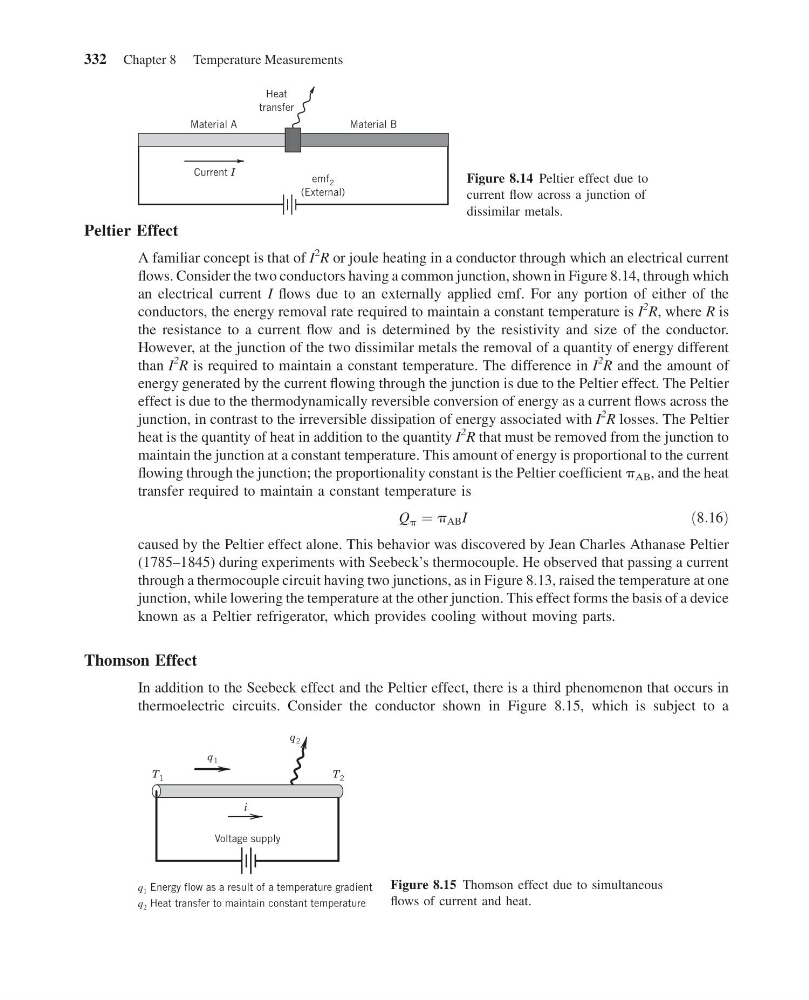
flows. Consider the two conductors having a common junction, shown in Figure 8.14, through which
an electrical current I flows due to an externally applied emf. For any portion of either of the
conductors, the energy removal rate required to maintain a constant temperature is I
2
R, where R is
the resistance to a current flow and is determined by the resistivity and size of the conductor.
However, at the junction of the two dissimilar metals the removal of a quantity of energy different
than I
2
R is required to maintain a constant temperature. The difference in I
2
R and the amount of
energy generated by the current flowing through the junction is due to the Peltier effect. The Peltier
effect is due to the thermodynamically reversible conversion of energy as a current flows across the
junction, in contrast to the irreversible dissipation of energy associated with I
2
R losses. The Peltier
heat is the quantity of heat in addition to the quantity I
2
R that must be removed from the junction to
maintain the junction at a constant temperature. This amount of energy is proportional to the current
flowing through the junction; the proportionality constant is the Peltier coefficient p AB , and the heat
transfer required to maintain a constant temperature is
Q p ¼ p AB I
ð8:16Þ
caused by the Peltier effect alone. This behavior was discovered by Jean Charles Athanase Peltier
(1785–1845) during experiments with Seebeck’s thermocouple. He observed that passing a current
through a thermocouple circuit having two junctions, as in Figure 8.13, raised the temperature at one
junction, while lowering the temperature at the other junction. This effect forms the basis of a device
known as a Peltier refrigerator, which provides cooling without moving parts.
Thomson Effect
In addition to the Seebeck effect and the Peltier effect, there is a third phenomenon that occurs in
thermoelectric circuits. Consider the conductor shown in Figure 8.15, which is subject to a
B
l
a
i
r
e
t
a
M
A
l
a
i
r
e
t
a
M
emf 2
(External)
Heat
transfer
Current I
Figure 8.14 Peltier effect due to
current flow across a junction of
dissimilar metals.
T 1
T 2
q 2
q 1
i
Voltage supply
q 1 Energy flow as a result of a temperature gradient
q 2 Heat transfer to maintain constant temperature
Figure 8.15 Thomson effect due to simultaneous
flows of current and heat.
332 Chapter 8 Temperature Measurements
14:53:57 Page 332
Peltier Effect
A familiar concept is that of I
2
R or joule heating in a conductor through which an electrical current
flows. Consider the two conductors having a common junction, shown in Figure 8.14, through which
an electrical current I flows due to an externally applied emf. For any portion of either of the
conductors, the energy removal rate required to maintain a constant temperature is I
2
R, where R is
the resistance to a current flow and is determined by the resistivity and size of the conductor.
However, at the junction of the two dissimilar metals the removal of a quantity of energy different
than I
2
R is required to maintain a constant temperature. The difference in I
2
R and the amount of
energy generated by the current flowing through the junction is due to the Peltier effect. The Peltier
effect is due to the thermodynamically reversible conversion of energy as a current flows across the
junction, in contrast to the irreversible dissipation of energy associated with I
2
R losses. The Peltier
heat is the quantity of heat in addition to the quantity I
2
R that must be removed from the junction to
maintain the junction at a constant temperature. This amount of energy is proportional to the current
flowing through the junction; the proportionality constant is the Peltier coefficient p AB , and the heat
transfer required to maintain a constant temperature is
Q p ¼ p AB I
ð8:16Þ
caused by the Peltier effect alone. This behavior was discovered by Jean Charles Athanase Peltier
(1785–1845) during experiments with Seebeck’s thermocouple. He observed that passing a current
through a thermocouple circuit having two junctions, as in Figure 8.13, raised the temperature at one
junction, while lowering the temperature at the other junction. This effect forms the basis of a device
known as a Peltier refrigerator, which provides cooling without moving parts.
Thomson Effect
In addition to the Seebeck effect and the Peltier effect, there is a third phenomenon that occurs in
thermoelectric circuits. Consider the conductor shown in Figure 8.15, which is subject to a
B
l
a
i
r
e
t
a
M
A
l
a
i
r
e
t
a
M
emf 2
(External)
Heat
transfer
Current I
Figure 8.14 Peltier effect due to
current flow across a junction of
dissimilar metals.
T 1
T 2
q 2
q 1
i
Voltage supply
q 1 Energy flow as a result of a temperature gradient
q 2 Heat transfer to maintain constant temperature
Figure 8.15 Thomson effect due to simultaneous
flows of current and heat.
332 Chapter 8 Temperature Measurements