

E1C08 09/14/2010
14:53:57 Page 331
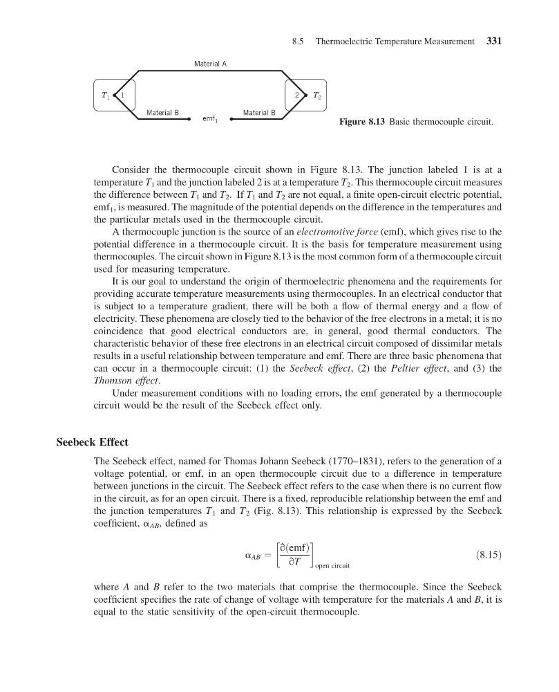
Consider the thermocouple circuit shown in Figure 8.13. The junction labeled 1 is at a
temperature T 1 and the junction labeled 2 is at a temperature T 2 . This thermocouple circuit measures
the difference between T 1 and T 2 . If T 1 and T 2 are not equal, a finite open-circuit electric potential,
emf 1 , is measured. The magnitude of the potential depends on the difference in the temperatures and
the particular metals used in the thermocouple circuit.
A thermocouple junction is the source of an electromotive force (emf), which gives rise to the
potential difference in a thermocouple circuit. It is the basis for temperature measurement using
thermocouples. The circuit shown in Figure 8.13 is the most common form of a thermocouple circuit
used for measuring temperature.
It is our goal to understand the origin of thermoelectric phenomena and the requirements for
providing accurate temperature measurements using thermocouples. In an electrical conductor that
is subject to a temperature gradient, there will be both a flow of thermal energy and a flow of
electricity. These phenomena are closely tied to the behavior of the free electrons in a metal; it is no
coincidence that good electrical conductors are, in general, good thermal conductors. The
characteristic behavior of these free electrons in an electrical circuit composed of dissimilar metals
results in a useful relationship between temperature and emf. There are three basic phenomena that
can occur in a thermocouple circuit: (1) the Seebeck effect, (2) the Peltier effect, and (3) the
Thomson effect.
Under measurement conditions with no loading errors, the emf generated by a thermocouple
circuit would be the result of the Seebeck effect only.
Seebeck Effect
The Seebeck effect, named for Thomas Johann Seebeck (1770–1831), refers to the generation of a
voltage potential, or emf, in an open thermocouple circuit due to a difference in temperature
between junctions in the circuit. The Seebeck effect refers to the case when there is no current flow
in the circuit, as for an open circuit. There is a fixed, reproducible relationship between the emf and
the junction temperatures T 1 and T 2 (Fig. 8.13). This relationship is expressed by the Seebeck
coefficient, a AB , defined as
a AB ¼
q emf
ð
Þ
qT
!
open circuit
ð8:15Þ
where A and B refer to the two materials that comprise the thermocouple. Since the Seebeck
coefficient specifies the rate of change of voltage with temperature for the materials A and B, it is
equal to the static sensitivity of the open-circuit thermocouple.
Material B
Material B
emf 1
2
1
Material A
T 1
T 2
Figure 8.13 Basic thermocouple circuit.
8.5 Thermoelectric Temperature Measurement 331
14:53:57 Page 331
Consider the thermocouple circuit shown in Figure 8.13. The junction labeled 1 is at a
temperature T 1 and the junction labeled 2 is at a temperature T 2 . This thermocouple circuit measures
the difference between T 1 and T 2 . If T 1 and T 2 are not equal, a finite open-circuit electric potential,
emf 1 , is measured. The magnitude of the potential depends on the difference in the temperatures and
the particular metals used in the thermocouple circuit.
A thermocouple junction is the source of an electromotive force (emf), which gives rise to the
potential difference in a thermocouple circuit. It is the basis for temperature measurement using
thermocouples. The circuit shown in Figure 8.13 is the most common form of a thermocouple circuit
used for measuring temperature.
It is our goal to understand the origin of thermoelectric phenomena and the requirements for
providing accurate temperature measurements using thermocouples. In an electrical conductor that
is subject to a temperature gradient, there will be both a flow of thermal energy and a flow of
electricity. These phenomena are closely tied to the behavior of the free electrons in a metal; it is no
coincidence that good electrical conductors are, in general, good thermal conductors. The
characteristic behavior of these free electrons in an electrical circuit composed of dissimilar metals
results in a useful relationship between temperature and emf. There are three basic phenomena that
can occur in a thermocouple circuit: (1) the Seebeck effect, (2) the Peltier effect, and (3) the
Thomson effect.
Under measurement conditions with no loading errors, the emf generated by a thermocouple
circuit would be the result of the Seebeck effect only.
Seebeck Effect
The Seebeck effect, named for Thomas Johann Seebeck (1770–1831), refers to the generation of a
voltage potential, or emf, in an open thermocouple circuit due to a difference in temperature
between junctions in the circuit. The Seebeck effect refers to the case when there is no current flow
in the circuit, as for an open circuit. There is a fixed, reproducible relationship between the emf and
the junction temperatures T 1 and T 2 (Fig. 8.13). This relationship is expressed by the Seebeck
coefficient, a AB , defined as
a AB ¼
q emf
ð
Þ
qT
!
open circuit
ð8:15Þ
where A and B refer to the two materials that comprise the thermocouple. Since the Seebeck
coefficient specifies the rate of change of voltage with temperature for the materials A and B, it is
equal to the static sensitivity of the open-circuit thermocouple.
Material B
Material B
emf 1
2
1
Material A
T 1
T 2
Figure 8.13 Basic thermocouple circuit.
8.5 Thermoelectric Temperature Measurement 331