

E1C08 09/14/2010
14:53:57 Page 333
longitudinal temperature gradient and also to a potential difference, such that there is a flow of
current and heat in the conductor. Again, to maintain a constant temperature in the conductor it is
found that a quantity of energy different than the joule heat, I
2
R, must be removed from the
conductor. First noted by William Thomson (1824–1907, Lord Kelvin from 1892) in 1851, this
energy is expressed in terms of the Thomson coefficient, s, as
Q s ¼ sI T 1 À T 2
ð
Þ
ð 8:17Þ
For a thermocouple circuit, all three of these effects may be present and may contribute to the overall
emf of the circuit.
Fundamental Thermocouple Laws
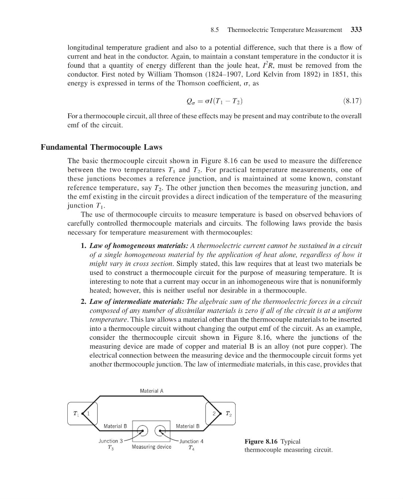
The basic thermocouple circuit shown in Figure 8.16 can be used to measure the difference
between the two temperatures T 1 and T 2 . For practical temperature measurements, one of
these junctions becomes a reference junction, and is maintained at some known, constant
reference temperature, say T 2 . The other junction then becomes the measuring junction, and
the emf existing in the circuit provides a direct indication of the temperature of the measuring
junction T 1 .
The use of thermocouple circuits to measure temperature is based on observed behaviors of
carefully controlled thermocouple materials and circuits. The following laws provide the basis
necessary for temperature measurement with thermocouples:
1. Law of homogeneous materials: A thermoelectric current cannot be sustained in a circuit
of a single homogeneous material by the application of heat alone, regardless of how it
might vary in cross section. Simply stated, this law requires that at least two materials be
used to construct a thermocouple circuit for the purpose of measuring temperature. It is
interesting to note that a current may occur in an inhomogeneous wire that is nonuniformly
heated; however, this is neither useful nor desirable in a thermocouple.
2. Law of intermediate materials: The algebraic sum of the thermoelectric forces in a circuit
composed of any number of dissimilar materials is zero if all of the circuit is at a uniform
temperature. This law allows a material other than the thermocouple materials to be inserted
into a thermocouple circuit without changing the output emf of the circuit. As an example,
consider the thermocouple circuit shown in Figure 8.16, where the junctions of the
measuring device are made of copper and material B is an alloy (not pure copper). The
electrical connection between the measuring device and the thermocouple circuit forms yet
another thermocouple junction. The law of intermediate materials, in this case, provides that
Material B
Material B
Measuring device
Junction 4
T 4
Junction 3
T 3
2
1
Material A
T 1
T 2
Figure 8.16 Typical
thermocouple measuring circuit.
8.5 Thermoelectric Temperature Measurement 333
14:53:57 Page 333
longitudinal temperature gradient and also to a potential difference, such that there is a flow of
current and heat in the conductor. Again, to maintain a constant temperature in the conductor it is
found that a quantity of energy different than the joule heat, I
2
R, must be removed from the
conductor. First noted by William Thomson (1824–1907, Lord Kelvin from 1892) in 1851, this
energy is expressed in terms of the Thomson coefficient, s, as
Q s ¼ sI T 1 À T 2
ð
Þ
ð 8:17Þ
For a thermocouple circuit, all three of these effects may be present and may contribute to the overall
emf of the circuit.
Fundamental Thermocouple Laws
The basic thermocouple circuit shown in Figure 8.16 can be used to measure the difference
between the two temperatures T 1 and T 2 . For practical temperature measurements, one of
these junctions becomes a reference junction, and is maintained at some known, constant
reference temperature, say T 2 . The other junction then becomes the measuring junction, and
the emf existing in the circuit provides a direct indication of the temperature of the measuring
junction T 1 .
The use of thermocouple circuits to measure temperature is based on observed behaviors of
carefully controlled thermocouple materials and circuits. The following laws provide the basis
necessary for temperature measurement with thermocouples:
1. Law of homogeneous materials: A thermoelectric current cannot be sustained in a circuit
of a single homogeneous material by the application of heat alone, regardless of how it
might vary in cross section. Simply stated, this law requires that at least two materials be
used to construct a thermocouple circuit for the purpose of measuring temperature. It is
interesting to note that a current may occur in an inhomogeneous wire that is nonuniformly
heated; however, this is neither useful nor desirable in a thermocouple.
2. Law of intermediate materials: The algebraic sum of the thermoelectric forces in a circuit
composed of any number of dissimilar materials is zero if all of the circuit is at a uniform
temperature. This law allows a material other than the thermocouple materials to be inserted
into a thermocouple circuit without changing the output emf of the circuit. As an example,
consider the thermocouple circuit shown in Figure 8.16, where the junctions of the
measuring device are made of copper and material B is an alloy (not pure copper). The
electrical connection between the measuring device and the thermocouple circuit forms yet
another thermocouple junction. The law of intermediate materials, in this case, provides that
Material B
Material B
Measuring device
Junction 4
T 4
Junction 3
T 3
2
1
Material A
T 1
T 2
Figure 8.16 Typical
thermocouple measuring circuit.
8.5 Thermoelectric Temperature Measurement 333