

E1C07 09/14/2010
14:43:51 Page 298
Example 7.8
The output from an analog device (nominal output impedance of 600 V) is the input to the 12-bit
A/D converter (nominal input impedance of 1 MV) of a data-acquisition system. For a 2-V signal,
will interstage loading be a problem?
KNOWN Z 1 ¼ 600 V
Z m ¼ l MV
E 1 ¼ 2 V
FIND e I
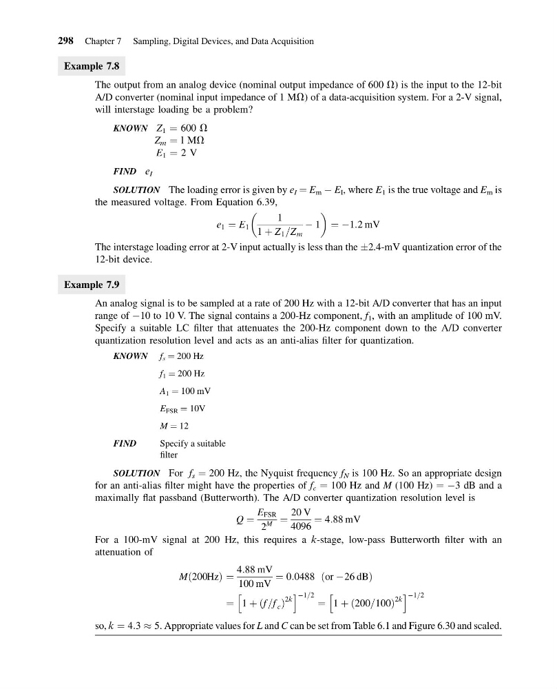
SOLUTION The loading error is given by e I ¼ E m À E I , where E 1 is the true voltage and E m is
the measured voltage. From Equation 6.39,
e 1 ¼ E 1
1
1 þ Z 1 =Z m
À 1
¼ À1:2 mV
The interstage loading error at 2-V input actually is less than the Æ2.4-mV quantization error of the
12-bit device.
Example 7.9
An analog signal is to be sampled at a rate of 200 Hz with a 12-bit A/D converter that has an input
range of À10 to 10 V. The signal contains a 200-Hz component, f 1 , with an amplitude of 100 mV.
Specify a suitable LC filter that attenuates the 200-Hz component down to the A/D converter
quantization resolution level and acts as an anti-alias filter for quantization.
KNOWN f s ¼ 200 Hz
f 1 ¼ 200 Hz
A 1 ¼ 100 mV
E FSR ¼ 10V
M ¼ 12
FIND
Specify a suitable
filter
SOLUTION For f s ¼ 200 Hz, the Nyquist frequency f N is 100 Hz. So an appropriate design
for an anti-alias filter might have the properties of f c ¼ 100 Hz and M (100 Hz) ¼ À3 dB and a
maximally flat passband (Butterworth). The A/D converter quantization resolution level is
Q ¼
E FSR
2
M ¼
20 V
4096
¼ 4:88 mV
For a 100-mV signal at 200 Hz, this requires a k-stage, low-pass Butterworth filter with an
attenuation of
Mð200HzÞ ¼
4:88 mV
100 mV
¼ 0:0488 ðor À26 dBÞ
¼ 1 þ f =f c
ð
Þ
2k
h
i À1=2 ¼ 1 þ 200=100
ð
Þ
2k
h
i À1=2
so, k ¼ 4:3 % 5. Appropriate values for L and C can be set from Table 6.1 and Figure 6.30 and scaled.
298 Chapter 7 Sampling, Digital Devices, and Data Acquisition
14:43:51 Page 298
Example 7.8
The output from an analog device (nominal output impedance of 600 V) is the input to the 12-bit
A/D converter (nominal input impedance of 1 MV) of a data-acquisition system. For a 2-V signal,
will interstage loading be a problem?
KNOWN Z 1 ¼ 600 V
Z m ¼ l MV
E 1 ¼ 2 V
FIND e I
SOLUTION The loading error is given by e I ¼ E m À E I , where E 1 is the true voltage and E m is
the measured voltage. From Equation 6.39,
e 1 ¼ E 1
1
1 þ Z 1 =Z m
À 1
¼ À1:2 mV
The interstage loading error at 2-V input actually is less than the Æ2.4-mV quantization error of the
12-bit device.
Example 7.9
An analog signal is to be sampled at a rate of 200 Hz with a 12-bit A/D converter that has an input
range of À10 to 10 V. The signal contains a 200-Hz component, f 1 , with an amplitude of 100 mV.
Specify a suitable LC filter that attenuates the 200-Hz component down to the A/D converter
quantization resolution level and acts as an anti-alias filter for quantization.
KNOWN f s ¼ 200 Hz
f 1 ¼ 200 Hz
A 1 ¼ 100 mV
E FSR ¼ 10V
M ¼ 12
FIND
Specify a suitable
filter
SOLUTION For f s ¼ 200 Hz, the Nyquist frequency f N is 100 Hz. So an appropriate design
for an anti-alias filter might have the properties of f c ¼ 100 Hz and M (100 Hz) ¼ À3 dB and a
maximally flat passband (Butterworth). The A/D converter quantization resolution level is
Q ¼
E FSR
2
M ¼
20 V
4096
¼ 4:88 mV
For a 100-mV signal at 200 Hz, this requires a k-stage, low-pass Butterworth filter with an
attenuation of
Mð200HzÞ ¼
4:88 mV
100 mV
¼ 0:0488 ðor À26 dBÞ
¼ 1 þ f =f c
ð
Þ
2k
h
i À1=2 ¼ 1 þ 200=100
ð
Þ
2k
h
i À1=2
so, k ¼ 4:3 % 5. Appropriate values for L and C can be set from Table 6.1 and Figure 6.30 and scaled.
298 Chapter 7 Sampling, Digital Devices, and Data Acquisition