

E1C07 09/14/2010
14:43:51 Page 297
activities and sequences all communications to and between devices, such as which bus device
transmits or receives and when. This is done along the bus management and handshaking lines. The
communication along the bus is bidirectional. Normally, ground true TTL logic (i.e.,
0:8 V HIGH; ! 2 V LOW) is used. The interplay between the controller and the devices on
the bus is controlled by software programs.
Example 7.7
A strain transducer has a static sensitivity of 2.5 V/unit strain (2.5 mV/me) and requires a supply
voltage of 5 VDC. It is to be connected to a DAS having a Æ5 V, 12-bit A/D converter and its signal
measured at 1000 Hz. The transducer signal is to be amplified and filtered. For an expected
measurement range of 1 to 500 me, specify appropriate values for amplifier gain, filter type, and
cutoff frequency, and show a signal flow diagram for the connections.
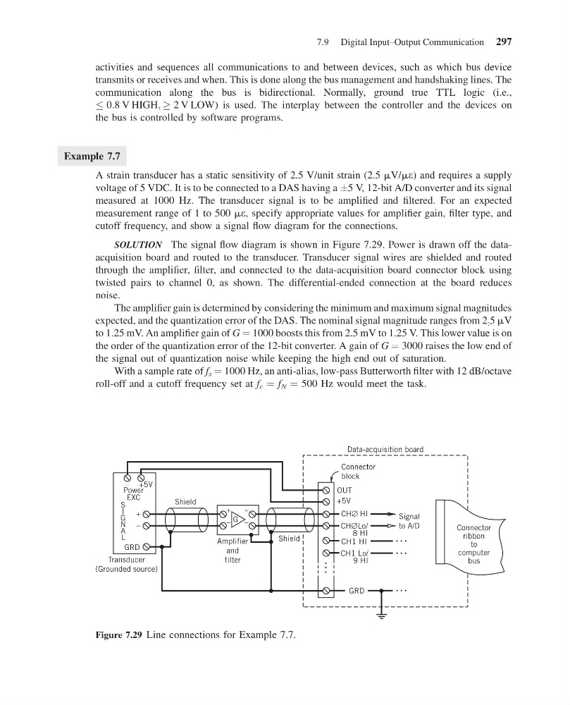
SOLUTION The signal flow diagram is shown in Figure 7.29. Power is drawn off the dataacquisition board and routed to the transducer. Transducer signal wires are shielded and routed
through the amplifier, filter, and connected to the data-acquisition board connector block using
twisted pairs to channel 0, as shown. The differential-ended connection at the board reduces
noise.
The amplifier gain is determined by considering the minimum and maximum signal magnitudes
expected, and the quantization error of the DAS. The nominal signal magnitude ranges from 2 : 5 mV
to 1.25 mV. An amplifier gain of G ¼ 1000 boosts this from 2.5 mV to 1.25 V. This lower value is on
the order of the quantization error of the 12-bit converter. A gain of G ¼ 3000 raises the low end of
the signal out of quantization noise while keeping the high end out of saturation.
With a sample rate of f s ¼ 1000 Hz, an anti-alias, low-pass Butterworth filter with 12 dB/octave
roll-off and a cutoff frequency set at f c ¼ f N ¼ 500 Hz would meet the task.
–
–
–
––
––
–
––
+5V
+5V
Power
EXC
S
I
G
N
A
L
GRD
GRD
Shield
Shield
G
Amplifier
and
filter
Connector
block
OUT
Data-acquisition board
Signal
to A/D
CH∅ HI
CH∅Lo/
8 HI
CH1 HI
CH1 Lo/
9 HI
Connector
ribbon
to
computer
bus
Transducer
(Grounded source)
Figure 7.29 Line connections for Example 7.7.
7.9 Digital Input–Output Communication 297
14:43:51 Page 297
activities and sequences all communications to and between devices, such as which bus device
transmits or receives and when. This is done along the bus management and handshaking lines. The
communication along the bus is bidirectional. Normally, ground true TTL logic (i.e.,
0:8 V HIGH; ! 2 V LOW) is used. The interplay between the controller and the devices on
the bus is controlled by software programs.
Example 7.7
A strain transducer has a static sensitivity of 2.5 V/unit strain (2.5 mV/me) and requires a supply
voltage of 5 VDC. It is to be connected to a DAS having a Æ5 V, 12-bit A/D converter and its signal
measured at 1000 Hz. The transducer signal is to be amplified and filtered. For an expected
measurement range of 1 to 500 me, specify appropriate values for amplifier gain, filter type, and
cutoff frequency, and show a signal flow diagram for the connections.
SOLUTION The signal flow diagram is shown in Figure 7.29. Power is drawn off the dataacquisition board and routed to the transducer. Transducer signal wires are shielded and routed
through the amplifier, filter, and connected to the data-acquisition board connector block using
twisted pairs to channel 0, as shown. The differential-ended connection at the board reduces
noise.
The amplifier gain is determined by considering the minimum and maximum signal magnitudes
expected, and the quantization error of the DAS. The nominal signal magnitude ranges from 2 : 5 mV
to 1.25 mV. An amplifier gain of G ¼ 1000 boosts this from 2.5 mV to 1.25 V. This lower value is on
the order of the quantization error of the 12-bit converter. A gain of G ¼ 3000 raises the low end of
the signal out of quantization noise while keeping the high end out of saturation.
With a sample rate of f s ¼ 1000 Hz, an anti-alias, low-pass Butterworth filter with 12 dB/octave
roll-off and a cutoff frequency set at f c ¼ f N ¼ 500 Hz would meet the task.
–
–
–
––
––
–
––
+5V
+5V
Power
EXC
S
I
G
N
A
L
GRD
GRD
Shield
Shield
G
Amplifier
and
filter
Connector
block
OUT
Data-acquisition board
Signal
to A/D
CH∅ HI
CH∅Lo/
8 HI
CH1 HI
CH1 Lo/
9 HI
Connector
ribbon
to
computer
bus
Transducer
(Grounded source)
Figure 7.29 Line connections for Example 7.7.
7.9 Digital Input–Output Communication 297