

E1C07 09/14/2010
14:43:51 Page 290
sample-hold time, sample rates of up to 333,000 Hz are possible. Input signals may be unipolar (e.g.,
0–10 V) or bipolar (e.g., Æ5 V). For the board shown, this allows input resolution for the 12-bit
converter with an E FSR ¼ 10 V range of approximately
Q ¼
E FSR
2
M ¼
10 V
2
12
¼ 2:44 mV
The amplifier permits signal conditioning with gains from G ¼ 0.5 to 1000. This improves the
minimum detectable voltage when set at maximum gain to
Q ¼
E FSR
G
ð Þ 2
M
À Á ¼
10 V
1000
ð
Þ 2
12
À Á ¼ 2:44 mV
Digital I/O can usually be accomplished through these boards for instrument control applications
and external triggering. For the board shown, 16-TTL compatible lines are available.
Single- and Differential-Ended Connections
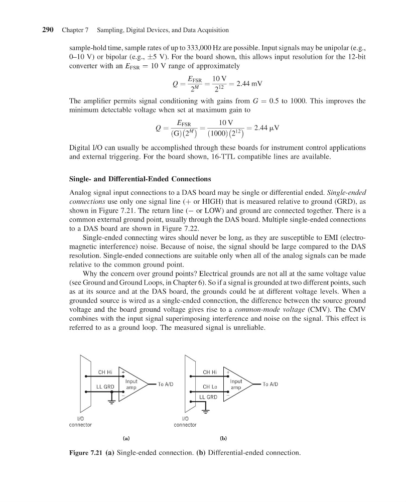
Analog signal input connections to a DAS board may be single or differential ended. Single-ended
connections use only one signal line (þ or HIGH) that is measured relative to ground (GRD), as
shown in Figure 7.21. The return line (À or LOW) and ground are connected together. There is a
common external ground point, usually through the DAS board. Multiple single-ended connections
to a DAS board are shown in Figure 7.22.
Single-ended connecting wires should never be long, as they are susceptible to EMI (electromagnetic interference) noise. Because of noise, the signal should be large compared to the DAS
resolution. Single-ended connections are suitable only when all of the analog signals can be made
relative to the common ground point.
Why the concern over ground points? Electrical grounds are not all at the same voltage value
(see Ground and Ground Loops, in Chapter 6). So if a signal is grounded at two different points, such
as at its source and at the DAS board, the grounds could be at different voltage levels. When a
grounded source is wired as a single-ended connection, the difference between the source ground
voltage and the board ground voltage gives rise to a common-mode voltage (CMV). The CMV
combines with the input signal superimposing interference and noise on the signal. This effect is
referred to as a ground loop. The measured signal is unreliable.
CH Hi
LL GRD
LL GRD
I/O
connector
To A/D
–
+
CH Hi
CH Lo
I/O
connector
To A/D
–
+
Input
amp
Input
amp
(b)
(a)
Figure 7.21 (a) Single-ended connection. (b) Differential-ended connection.
290 Chapter 7 Sampling, Digital Devices, and Data Acquisition
14:43:51 Page 290
sample-hold time, sample rates of up to 333,000 Hz are possible. Input signals may be unipolar (e.g.,
0–10 V) or bipolar (e.g., Æ5 V). For the board shown, this allows input resolution for the 12-bit
converter with an E FSR ¼ 10 V range of approximately
Q ¼
E FSR
2
M ¼
10 V
2
12
¼ 2:44 mV
The amplifier permits signal conditioning with gains from G ¼ 0.5 to 1000. This improves the
minimum detectable voltage when set at maximum gain to
Q ¼
E FSR
G
ð Þ 2
M
À Á ¼
10 V
1000
ð
Þ 2
12
À Á ¼ 2:44 mV
Digital I/O can usually be accomplished through these boards for instrument control applications
and external triggering. For the board shown, 16-TTL compatible lines are available.
Single- and Differential-Ended Connections
Analog signal input connections to a DAS board may be single or differential ended. Single-ended
connections use only one signal line (þ or HIGH) that is measured relative to ground (GRD), as
shown in Figure 7.21. The return line (À or LOW) and ground are connected together. There is a
common external ground point, usually through the DAS board. Multiple single-ended connections
to a DAS board are shown in Figure 7.22.
Single-ended connecting wires should never be long, as they are susceptible to EMI (electromagnetic interference) noise. Because of noise, the signal should be large compared to the DAS
resolution. Single-ended connections are suitable only when all of the analog signals can be made
relative to the common ground point.
Why the concern over ground points? Electrical grounds are not all at the same voltage value
(see Ground and Ground Loops, in Chapter 6). So if a signal is grounded at two different points, such
as at its source and at the DAS board, the grounds could be at different voltage levels. When a
grounded source is wired as a single-ended connection, the difference between the source ground
voltage and the board ground voltage gives rise to a common-mode voltage (CMV). The CMV
combines with the input signal superimposing interference and noise on the signal. This effect is
referred to as a ground loop. The measured signal is unreliable.
CH Hi
LL GRD
LL GRD
I/O
connector
To A/D
–
+
CH Hi
CH Lo
I/O
connector
To A/D
–
+
Input
amp
Input
amp
(b)
(a)
Figure 7.21 (a) Single-ended connection. (b) Differential-ended connection.
290 Chapter 7 Sampling, Digital Devices, and Data Acquisition