

E1C07 09/14/2010
14:43:50 Page 289
M
P
X
Instrument
amp
Digital
I/O
Analog
out
Analog
input
Interrupt
Interrupt logic
control
DMA logic
control
DMA select
Bus
interface
and
buffers
Bus and circuit
power
Bus clock
Plug connection
PC bus
Status
register
Control
register
DAC
ADC
SHC
DAS board bus
G
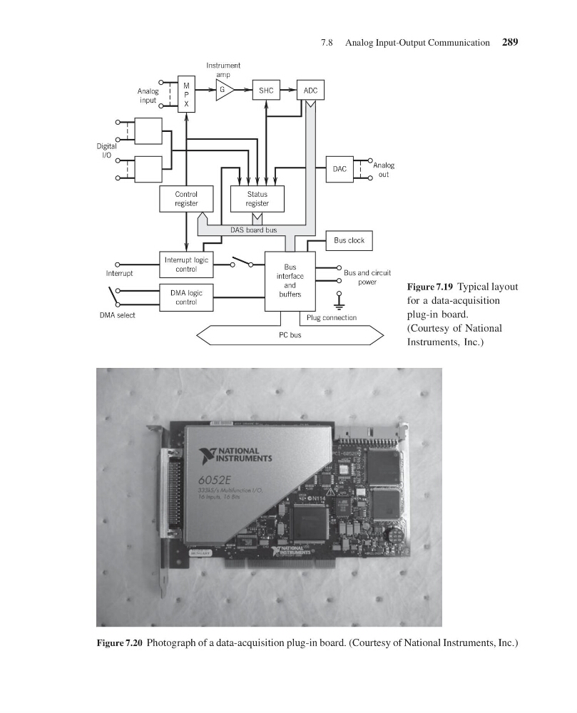
Figure 7.19 Typical layout
for a data-acquisition
plug-in board.
(Courtesy of National
Instruments, Inc.)
Figure 7.20 Photograph of a data-acquisition plug-in board. (Courtesy of National Instruments, Inc.)
7.8 Analog Input-Output Communication 289
14:43:50 Page 289
M
P
X
Instrument
amp
Digital
I/O
Analog
out
Analog
input
Interrupt
Interrupt logic
control
DMA logic
control
DMA select
Bus
interface
and
buffers
Bus and circuit
power
Bus clock
Plug connection
PC bus
Status
register
Control
register
DAC
ADC
SHC
DAS board bus
G
Figure 7.19 Typical layout
for a data-acquisition
plug-in board.
(Courtesy of National
Instruments, Inc.)
Figure 7.20 Photograph of a data-acquisition plug-in board. (Courtesy of National Instruments, Inc.)
7.8 Analog Input-Output Communication 289