

E1C07 09/14/2010
14:43:50 Page 288
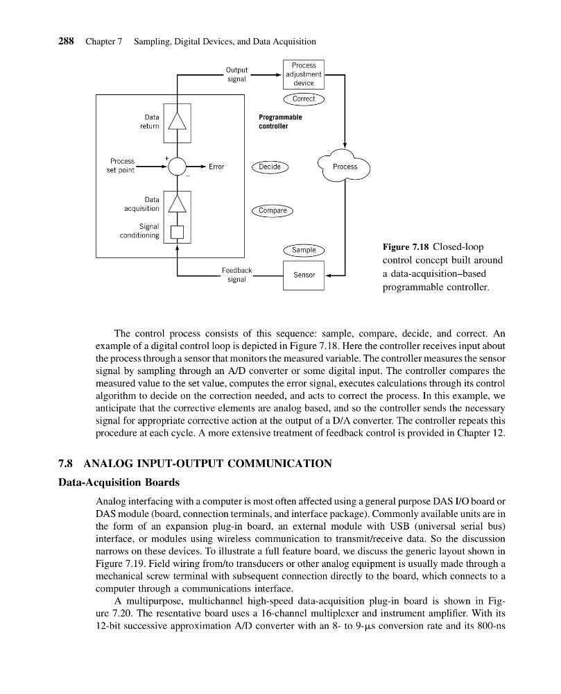
The control process consists of this sequence: sample, compare, decide, and correct. An
example of a digital control loop is depicted in Figure 7.18. Here the controller receives input about
the process through a sensor that monitors the measured variable. The controller measures the sensor
signal by sampling through an A/D converter or some digital input. The controller compares the
measured value to the set value, computes the error signal, executes calculations through its control
algorithm to decide on the correction needed, and acts to correct the process. In this example, we
anticipate that the corrective elements are analog based, and so the controller sends the necessary
signal for appropriate corrective action at the output of a D/A converter. The controller repeats this
procedure at each cycle. A more extensive treatment of feedback control is provided in Chapter 12.
7.8 ANALOG INPUT-OUTPUT COMMUNICATION
Data-Acquisition Boards
Analog interfacing with a computer is most often affected using a general purpose DAS I/O board or
DAS module (board, connection terminals, and interface package). Commonly available units are in
the form of an expansion plug-in board, an external module with USB (universal serial bus)
interface, or modules using wireless communication to transmit/receive data. So the discussion
narrows on these devices. To illustrate a full feature board, we discuss the generic layout shown in
Figure 7.19. Field wiring from/to transducers or other analog equipment is usually made through a
mechanical screw terminal with subsequent connection directly to the board, which connects to a
computer through a communications interface.
A multipurpose, multichannel high-speed data-acquisition plug-in board is shown in Figure 7.20. The resentative board uses a 16-channel multiplexer and instrument amplifier. With its
12-bit successive approximation A/D converter with an 8- to 9-ms conversion rate and its 800-ns
Error
–
+
Decide
Compare
Process
set point
Data
return
Programmable
controller
Data
acquisition
Signal
conditioning
Feedback
signal
Sensor
Process
adjustment
device
Output
signal
Sample
Correct
Process
Figure 7.18 Closed-loop
control concept built around
a data-acquisition–based
programmable controller.
288 Chapter 7 Sampling, Digital Devices, and Data Acquisition
14:43:50 Page 288
The control process consists of this sequence: sample, compare, decide, and correct. An
example of a digital control loop is depicted in Figure 7.18. Here the controller receives input about
the process through a sensor that monitors the measured variable. The controller measures the sensor
signal by sampling through an A/D converter or some digital input. The controller compares the
measured value to the set value, computes the error signal, executes calculations through its control
algorithm to decide on the correction needed, and acts to correct the process. In this example, we
anticipate that the corrective elements are analog based, and so the controller sends the necessary
signal for appropriate corrective action at the output of a D/A converter. The controller repeats this
procedure at each cycle. A more extensive treatment of feedback control is provided in Chapter 12.
7.8 ANALOG INPUT-OUTPUT COMMUNICATION
Data-Acquisition Boards
Analog interfacing with a computer is most often affected using a general purpose DAS I/O board or
DAS module (board, connection terminals, and interface package). Commonly available units are in
the form of an expansion plug-in board, an external module with USB (universal serial bus)
interface, or modules using wireless communication to transmit/receive data. So the discussion
narrows on these devices. To illustrate a full feature board, we discuss the generic layout shown in
Figure 7.19. Field wiring from/to transducers or other analog equipment is usually made through a
mechanical screw terminal with subsequent connection directly to the board, which connects to a
computer through a communications interface.
A multipurpose, multichannel high-speed data-acquisition plug-in board is shown in Figure 7.20. The resentative board uses a 16-channel multiplexer and instrument amplifier. With its
12-bit successive approximation A/D converter with an 8- to 9-ms conversion rate and its 800-ns
Error
–
+
Decide
Compare
Process
set point
Data
return
Programmable
controller
Data
acquisition
Signal
conditioning
Feedback
signal
Sensor
Process
adjustment
device
Output
signal
Sample
Correct
Process
Figure 7.18 Closed-loop
control concept built around
a data-acquisition–based
programmable controller.
288 Chapter 7 Sampling, Digital Devices, and Data Acquisition