

E1C07 09/14/2010
14:43:50 Page 287
A/D Converters
High-speed data-acquisition boards employ successive approximation converters with conversion
rates typically up to the 100-kHz to 10-MHz range or parallel converters for rates up to and over 150
MHz. Low-level voltage measurements require the high noise rejection of the dual-ramp converter.
Here the trade-off is in speed, with maximum conversion rates of 1 to 100 Hz more common.
D/A Converters
A digital-to-analog converter permits a DAS to convert digital numbers into analog voltages, which
might be used for process control, such as to change a process variable, activate a device, or to drive
a sensor positioning motor. The digital-to-analog signal is initiated by software or a controller.
Digital Input/Output
Digital signals are composed of discrete states, either high or low. Digital input/output lines may be
used to communicate between instruments (see Section 7.9), control relays (to power equipment on
or off), or indicate the state or status of a device. A common way to transmit digital information is
the use of a 5-V TTL signal (e.g., see Fig. 7.5).
Digital I/O signals may be as a single state (HIGH or LOW; 5 Vor 0 V) or as a series of pulses of
HIGH/LOW states. The single-state signal might be used to operate a switch or relay, or to signal an
alarm. A series of pulses transmits a data series. Gate-pulse counting entails counting pulses that
occur over a specified period of time. This enables frequency determination (number of pulses/unit
time) and counting/timing applications. Pulse stepping, sending a predetermined number of pulses
in a series, is used to drive stepper motors and servos. Several I/O ports can be grouped to send
parallel information.
Closed-Loop Controller
In closed-loop control, the controller is used to compare the state of a process, as determined through
the value of a measured variable, with the value of a set condition and to take appropriate action to
reduce the difference in value of the two. This difference in value is called the error signal. This error
can change as part of the dynamics of the process, which causes the measured variable to change
value, or because the set condition itself is changed. The controller action is to adjust the process so
as to keep the error within a desired range.
E 1
E 2
E 3
E 4
E o
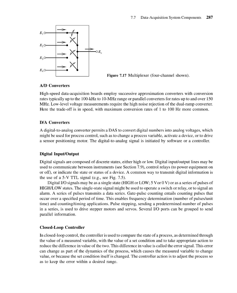
Figure 7.17 Multiplexer (four-channel shown).
7.7 Data-Acquisition System Components 287
14:43:50 Page 287
A/D Converters
High-speed data-acquisition boards employ successive approximation converters with conversion
rates typically up to the 100-kHz to 10-MHz range or parallel converters for rates up to and over 150
MHz. Low-level voltage measurements require the high noise rejection of the dual-ramp converter.
Here the trade-off is in speed, with maximum conversion rates of 1 to 100 Hz more common.
D/A Converters
A digital-to-analog converter permits a DAS to convert digital numbers into analog voltages, which
might be used for process control, such as to change a process variable, activate a device, or to drive
a sensor positioning motor. The digital-to-analog signal is initiated by software or a controller.
Digital Input/Output
Digital signals are composed of discrete states, either high or low. Digital input/output lines may be
used to communicate between instruments (see Section 7.9), control relays (to power equipment on
or off), or indicate the state or status of a device. A common way to transmit digital information is
the use of a 5-V TTL signal (e.g., see Fig. 7.5).
Digital I/O signals may be as a single state (HIGH or LOW; 5 Vor 0 V) or as a series of pulses of
HIGH/LOW states. The single-state signal might be used to operate a switch or relay, or to signal an
alarm. A series of pulses transmits a data series. Gate-pulse counting entails counting pulses that
occur over a specified period of time. This enables frequency determination (number of pulses/unit
time) and counting/timing applications. Pulse stepping, sending a predetermined number of pulses
in a series, is used to drive stepper motors and servos. Several I/O ports can be grouped to send
parallel information.
Closed-Loop Controller
In closed-loop control, the controller is used to compare the state of a process, as determined through
the value of a measured variable, with the value of a set condition and to take appropriate action to
reduce the difference in value of the two. This difference in value is called the error signal. This error
can change as part of the dynamics of the process, which causes the measured variable to change
value, or because the set condition itself is changed. The controller action is to adjust the process so
as to keep the error within a desired range.
E 1
E 2
E 3
E 4
E o
Figure 7.17 Multiplexer (four-channel shown).
7.7 Data-Acquisition System Components 287