

E1C07 09/14/2010
14:43:50 Page 286
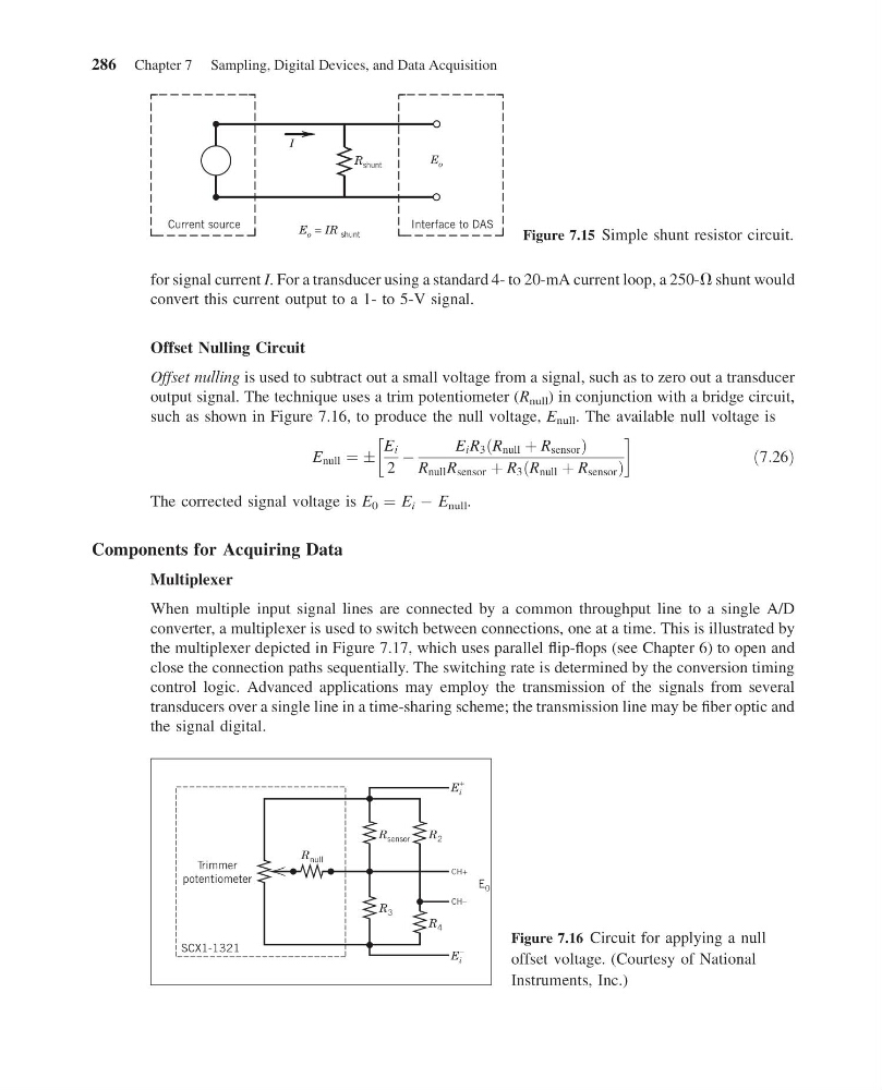
for signal current I. For a transducer using a standard 4- to 20-mA current loop, a 250-V shunt would
convert this current output to a 1- to 5-V signal.
Offset Nulling Circuit
Offset nulling is used to subtract out a small voltage from a signal, such as to zero out a transducer
output signal. The technique uses a trim potentiometer (R null ) in conjunction with a bridge circuit,
such as shown in Figure 7.16, to produce the null voltage, E null . The available null voltage is
E null ¼ Æ
E i
2
À
E i R 3 R null þ R sensor
ð
Þ
R null R sensor þ R 3 R null þ R sensor
ð
Þ
!
ð7:26Þ
The corrected signal voltage is E 0 ¼ E i À E null .
Components for Acquiring Data
Multiplexer
When multiple input signal lines are connected by a common throughput line to a single A/D
converter, a multiplexer is used to switch between connections, one at a time. This is illustrated by
the multiplexer depicted in Figure 7.17, which uses parallel flip-flops (see Chapter 6) to open and
close the connection paths sequentially. The switching rate is determined by the conversion timing
control logic. Advanced applications may employ the transmission of the signals from several
transducers over a single line in a time-sharing scheme; the transmission line may be fiber optic and
the signal digital.
R shunt
Interface to DAS
Current source
E o
I
E o = IR shunt
Figure 7.15 Simple shunt resistor circuit.
R null
R sensor
R 2
R 3
R 4
E i
+
E i
–
E 0
CH+
CH–
Trimmer
potentiometer
SCX1-1321
Figure 7.16 Circuit for applying a null
offset voltage. (Courtesy of National
Instruments, Inc.)
286 Chapter 7 Sampling, Digital Devices, and Data Acquisition
14:43:50 Page 286
for signal current I. For a transducer using a standard 4- to 20-mA current loop, a 250-V shunt would
convert this current output to a 1- to 5-V signal.
Offset Nulling Circuit
Offset nulling is used to subtract out a small voltage from a signal, such as to zero out a transducer
output signal. The technique uses a trim potentiometer (R null ) in conjunction with a bridge circuit,
such as shown in Figure 7.16, to produce the null voltage, E null . The available null voltage is
E null ¼ Æ
E i
2
À
E i R 3 R null þ R sensor
ð
Þ
R null R sensor þ R 3 R null þ R sensor
ð
Þ
!
ð7:26Þ
The corrected signal voltage is E 0 ¼ E i À E null .
Components for Acquiring Data
Multiplexer
When multiple input signal lines are connected by a common throughput line to a single A/D
converter, a multiplexer is used to switch between connections, one at a time. This is illustrated by
the multiplexer depicted in Figure 7.17, which uses parallel flip-flops (see Chapter 6) to open and
close the connection paths sequentially. The switching rate is determined by the conversion timing
control logic. Advanced applications may employ the transmission of the signals from several
transducers over a single line in a time-sharing scheme; the transmission line may be fiber optic and
the signal digital.
R shunt
Interface to DAS
Current source
E o
I
E o = IR shunt
Figure 7.15 Simple shunt resistor circuit.
R null
R sensor
R 2
R 3
R 4
E i
+
E i
–
E 0
CH+
CH–
Trimmer
potentiometer
SCX1-1321
Figure 7.16 Circuit for applying a null
offset voltage. (Courtesy of National
Instruments, Inc.)
286 Chapter 7 Sampling, Digital Devices, and Data Acquisition