

E1C07 09/14/2010
14:43:51 Page 291
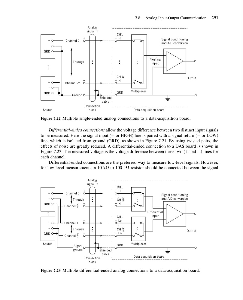
Differential-ended connections allow the voltage difference between two distinct input signals
to be measured. Here the signal input (þ or HIGH) line is paired with a signal return (À or LOW)
line, which is isolated from ground (GRD), as shown in Figure 7.21. By using twisted pairs, the
effects of noise are greatly reduced. A differential-ended connection to a DAS board is shown in
Figure 7.23. The measured voltage is the voltage difference between these two (þ and À) lines for
each channel.
Differential-ended connections are the preferred way to measure low-level signals. However,
for low-level measurements, a 10-kV to 100-kV resistor should be connected between the signal
CH1
Hi
Channel 1
+
+
+
–
Through
GRD
CH N
Hi
GRD
Multiplexer
Output
Floating
input
Signal conditioning
and A/D conversion
Data-acquisition board
Source
+
+
–
Channel N
Ground
Shielded
cable
Analog
signal in
Connection
block
+
GRD
Figure 7.22 Multiple single-ended analog connections to a data-acquisition board.
CH1
Hi
Channel 1
+
CH
Hi
+
+
+
–
Channel
Through
+
GRD
CH1
Lo
Channel 1
–
CH
Lo
GRD
Multiplexer
Output
Differential
input
Signal conditioning
and A/D conversion
Source
Data-acquisition board
–
–
+
–
Channel
Through
Signal
ground
Shielded
cable
Analog
signal in
Connection
block
–
GRD
N
2
N
2
N
2
N
2
Figure 7.23 Multiple differential-ended analog connections to a data-acquisition board.
7.8 Analog Input-Output Communication 291
14:43:51 Page 291
Differential-ended connections allow the voltage difference between two distinct input signals
to be measured. Here the signal input (þ or HIGH) line is paired with a signal return (À or LOW)
line, which is isolated from ground (GRD), as shown in Figure 7.21. By using twisted pairs, the
effects of noise are greatly reduced. A differential-ended connection to a DAS board is shown in
Figure 7.23. The measured voltage is the voltage difference between these two (þ and À) lines for
each channel.
Differential-ended connections are the preferred way to measure low-level signals. However,
for low-level measurements, a 10-kV to 100-kV resistor should be connected between the signal
CH1
Hi
Channel 1
+
+
+
–
Through
GRD
CH N
Hi
GRD
Multiplexer
Output
Floating
input
Signal conditioning
and A/D conversion
Data-acquisition board
Source
+
+
–
Channel N
Ground
Shielded
cable
Analog
signal in
Connection
block
+
GRD
Figure 7.22 Multiple single-ended analog connections to a data-acquisition board.
CH1
Hi
Channel 1
+
CH
Hi
+
+
+
–
Channel
Through
+
GRD
CH1
Lo
Channel 1
–
CH
Lo
GRD
Multiplexer
Output
Differential
input
Signal conditioning
and A/D conversion
Source
Data-acquisition board
–
–
+
–
Channel
Through
Signal
ground
Shielded
cable
Analog
signal in
Connection
block
–
GRD
N
2
N
2
N
2
N
2
Figure 7.23 Multiple differential-ended analog connections to a data-acquisition board.
7.8 Analog Input-Output Communication 291