

E1C07 09/14/2010
14:43:50 Page 280
The accuracy of this single ramp operation is limited by the accuracy of the timing clock and the
known values and constancy of the capacitor and the charging current. Increased accuracy can be
achieved using a dual ramp converter, sometimes referred to as a dual-slope integrator, in which the
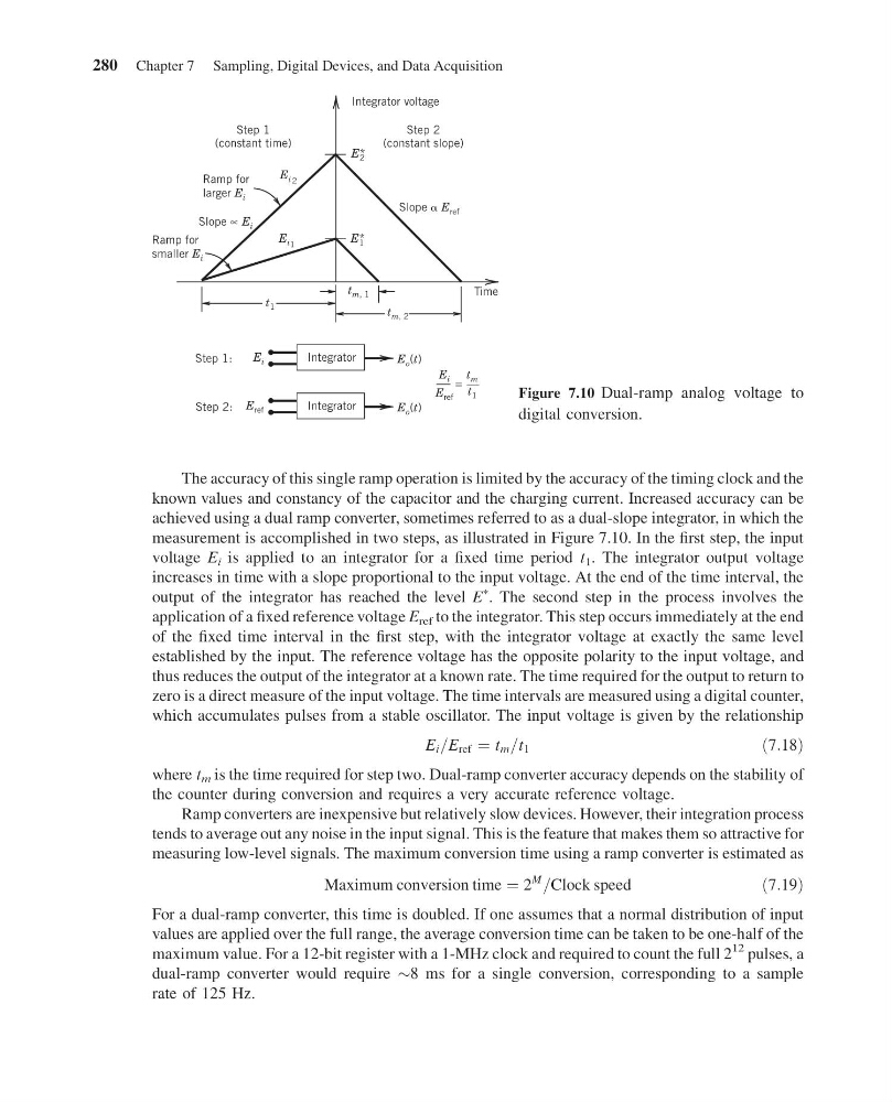
measurement is accomplished in two steps, as illustrated in Figure 7.10. In the first step, the input
voltage E i is applied to an integrator for a fixed time period t 1 . The integrator output voltage
increases in time with a slope proportional to the input voltage. At the end of the time interval, the
output of the integrator has reached the level E
à . The second step in the process involves the
application of a fixed reference voltage E ref to the integrator. This step occurs immediately at the end
of the fixed time interval in the first step, with the integrator voltage at exactly the same level
established by the input. The reference voltage has the opposite polarity to the input voltage, and
thus reduces the output of the integrator at a known rate. The time required for the output to return to
zero is a direct measure of the input voltage. The time intervals are measured using a digital counter,
which accumulates pulses from a stable oscillator. The input voltage is given by the relationship
E i =E ref ¼ t m =t 1
ð7:18Þ
where t m is the time required for step two. Dual-ramp converter accuracy depends on the stability of
the counter during conversion and requires a very accurate reference voltage.
Ramp converters are inexpensive but relatively slow devices. However, their integration process
tends to average out any noise in the input signal. This is the feature that makes them so attractive for
measuring low-level signals. The maximum conversion time using a ramp converter is estimated as
Maximum conversion time ¼ 2
M
=Clock speed
ð7:19Þ
For a dual-ramp converter, this time is doubled. If one assumes that a normal distribution of input
values are applied over the full range, the average conversion time can be taken to be one-half of the
maximum value. For a 12-bit register with a 1-MHz clock and required to count the full 2
12 pulses, a
dual-ramp converter would require $8 ms for a single conversion, corresponding to a sample
rate of 125 Hz.
Step 1:
Step 2:
Time
E i2
E i1
E i
E ref
E o (t)
E o (t)
E* 2
E* 1
E i
E ref
t m
t 1
=
t 1
t m, 2
t m, 1
Slope E ref
Slope ∝ E i
Step 2
(constant slope)
Step 1
(constant time)
Ramp for
larger E i
Ramp for
smaller E i
Integrator voltage
Integrator
Integrator
Figure 7.10 Dual-ramp analog voltage to
digital conversion.
280 Chapter 7 Sampling, Digital Devices, and Data Acquisition
14:43:50 Page 280
The accuracy of this single ramp operation is limited by the accuracy of the timing clock and the
known values and constancy of the capacitor and the charging current. Increased accuracy can be
achieved using a dual ramp converter, sometimes referred to as a dual-slope integrator, in which the
measurement is accomplished in two steps, as illustrated in Figure 7.10. In the first step, the input
voltage E i is applied to an integrator for a fixed time period t 1 . The integrator output voltage
increases in time with a slope proportional to the input voltage. At the end of the time interval, the
output of the integrator has reached the level E
à . The second step in the process involves the
application of a fixed reference voltage E ref to the integrator. This step occurs immediately at the end
of the fixed time interval in the first step, with the integrator voltage at exactly the same level
established by the input. The reference voltage has the opposite polarity to the input voltage, and
thus reduces the output of the integrator at a known rate. The time required for the output to return to
zero is a direct measure of the input voltage. The time intervals are measured using a digital counter,
which accumulates pulses from a stable oscillator. The input voltage is given by the relationship
E i =E ref ¼ t m =t 1
ð7:18Þ
where t m is the time required for step two. Dual-ramp converter accuracy depends on the stability of
the counter during conversion and requires a very accurate reference voltage.
Ramp converters are inexpensive but relatively slow devices. However, their integration process
tends to average out any noise in the input signal. This is the feature that makes them so attractive for
measuring low-level signals. The maximum conversion time using a ramp converter is estimated as
Maximum conversion time ¼ 2
M
=Clock speed
ð7:19Þ
For a dual-ramp converter, this time is doubled. If one assumes that a normal distribution of input
values are applied over the full range, the average conversion time can be taken to be one-half of the
maximum value. For a 12-bit register with a 1-MHz clock and required to count the full 2
12 pulses, a
dual-ramp converter would require $8 ms for a single conversion, corresponding to a sample
rate of 125 Hz.
Step 1:
Step 2:
Time
E i2
E i1
E i
E ref
E o (t)
E o (t)
E* 2
E* 1
E i
E ref
t m
t 1
=
t 1
t m, 2
t m, 1
Slope E ref
Slope ∝ E i
Step 2
(constant slope)
Step 1
(constant time)
Ramp for
larger E i
Ramp for
smaller E i
Integrator voltage
Integrator
Integrator
Figure 7.10 Dual-ramp analog voltage to
digital conversion.
280 Chapter 7 Sampling, Digital Devices, and Data Acquisition