

E1C07 09/14/2010
14:43:50 Page 281
Parallel Converters
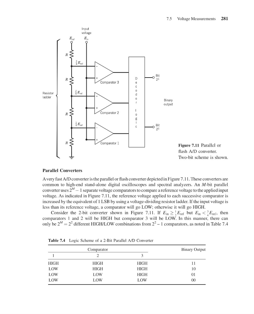
Avery fast A/D converter is the parallel or flash converter depicted in Figure 7.11. These converters are
common to high-end stand-alone digital oscilloscopes and spectral analyzers. An M-bit parallel
converter uses 2
M
À 1 separate voltage comparators to compare a reference voltage to the applied input
voltage. As indicated in Figure 7.11, the reference voltage applied to each successive comparator is
increased by the equivalent of 1 LSB by using a voltage-dividing resistor ladder. If the input voltage is
less than its reference voltage, a comparator will go LOW; otherwise it will go HIGH.
Consider the 2-bit converter shown in Figure 7.11. If E in !
1
2
E ref but E in <
3
4
E ref , then
comparators 1 and 2 will be HIGH but comparator 3 will be LOW. In this manner, there can
only be 2
M
¼ 2
2 different HIGH/LOW combinations from 2
2 – 1 comparators, as noted in Table 7.4
R
R
R
R
Resistor
ladder
E ref
E in
Input
voltage
–
+
–
+
–
+
Comparator 3
Comparator 2
Comparator 1
D
e
c
o
d
e
r
l
o
g
i
c
Bit
2 1
Bit
2 0
Binary
output
2
4 E ref
3
4 E ref
1
4 E ref
Figure 7.11 Parallel or
flash A/D converter.
Two-bit scheme is shown.
Table 7.4 Logic Scheme of a 2-Bit Parallel A/D Converter
Comparator
Binary Output
1
2
3
HIGH
HIGH
HIGH
11
LOW
HIGH
HIGH
10
LOW
LOW
HIGH
01
LOW
LOW
LOW
00
7.5 Voltage Measurements 281
14:43:50 Page 281
Parallel Converters
Avery fast A/D converter is the parallel or flash converter depicted in Figure 7.11. These converters are
common to high-end stand-alone digital oscilloscopes and spectral analyzers. An M-bit parallel
converter uses 2
M
À 1 separate voltage comparators to compare a reference voltage to the applied input
voltage. As indicated in Figure 7.11, the reference voltage applied to each successive comparator is
increased by the equivalent of 1 LSB by using a voltage-dividing resistor ladder. If the input voltage is
less than its reference voltage, a comparator will go LOW; otherwise it will go HIGH.
Consider the 2-bit converter shown in Figure 7.11. If E in !
1
2
E ref but E in <
3
4
E ref , then
comparators 1 and 2 will be HIGH but comparator 3 will be LOW. In this manner, there can
only be 2
M
¼ 2
2 different HIGH/LOW combinations from 2
2 – 1 comparators, as noted in Table 7.4
R
R
R
R
Resistor
ladder
E ref
E in
Input
voltage
–
+
–
+
–
+
Comparator 3
Comparator 2
Comparator 1
D
e
c
o
d
e
r
l
o
g
i
c
Bit
2 1
Bit
2 0
Binary
output
2
4 E ref
3
4 E ref
1
4 E ref
Figure 7.11 Parallel or
flash A/D converter.
Two-bit scheme is shown.
Table 7.4 Logic Scheme of a 2-Bit Parallel A/D Converter
Comparator
Binary Output
1
2
3
HIGH
HIGH
HIGH
11
LOW
HIGH
HIGH
10
LOW
LOW
HIGH
01
LOW
LOW
LOW
00
7.5 Voltage Measurements 281