

E1C07 09/14/2010
14:43:49 Page 276
Example 7.4
Compute the relative effect of quantization error (e Q /E i ) in the quantization of a 100-mV and a 1-V
analog signal using an 8-bit and a 12-bit A/D converter, both having a full-scale range of 0 to 10 V.
KNOWN E i ¼ 100 mV and 1V
M ¼ 8 and 12
E FSR ¼ 0-10 V
FIND e Q /E i , where e Q is the quantization error
SOLUTION The resolutions for the 8-bit and 12-bit converters can be estimated from Equation
7.14 as
Q 8 ¼
E FSR
2
8
¼
10
256
¼ 39 mV
Q 12 ¼
E FSR
2
12
¼
10
4096
¼ 2:4 mV
Assume the A/D converter is designed so that the absolute quantization error is given by Æ
1
2 Q. The
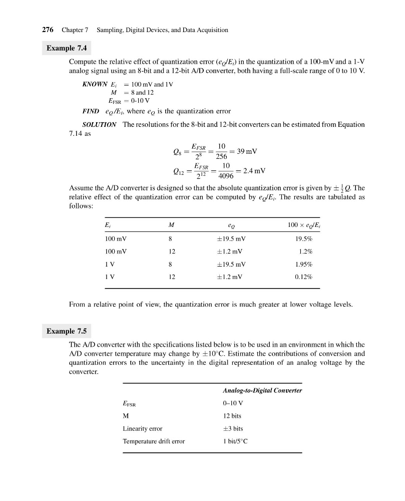
relative effect of the quantization error can be computed by e Q /E i . The results are tabulated as
follows:
E i
M
e Q
100 Â e Q /E i
100 mV
8
Æ19.5 mV
19.5%
100 mV
12
Æ1.2 mV
1.2%
1 V
8
Æ19.5 mV
1.95%
1 V
12
Æ1.2 mV
0.12%
From a relative point of view, the quantization error is much greater at lower voltage levels.
Example 7.5
The A/D converter with the specifications listed below is to be used in an environment in which the
A/D converter temperature may change by Æ10
C. Estimate the contributions of conversion and
quantization errors to the uncertainty in the digital representation of an analog voltage by the
converter.
Analog-to-Digital Converter
E FSR
0–10 V
M
12 bits
Linearity error
Æ3 bits
Temperature drift error
1 bit/5
C
276 Chapter 7 Sampling, Digital Devices, and Data Acquisition
14:43:49 Page 276
Example 7.4
Compute the relative effect of quantization error (e Q /E i ) in the quantization of a 100-mV and a 1-V
analog signal using an 8-bit and a 12-bit A/D converter, both having a full-scale range of 0 to 10 V.
KNOWN E i ¼ 100 mV and 1V
M ¼ 8 and 12
E FSR ¼ 0-10 V
FIND e Q /E i , where e Q is the quantization error
SOLUTION The resolutions for the 8-bit and 12-bit converters can be estimated from Equation
7.14 as
Q 8 ¼
E FSR
2
8
¼
10
256
¼ 39 mV
Q 12 ¼
E FSR
2
12
¼
10
4096
¼ 2:4 mV
Assume the A/D converter is designed so that the absolute quantization error is given by Æ
1
2 Q. The
relative effect of the quantization error can be computed by e Q /E i . The results are tabulated as
follows:
E i
M
e Q
100 Â e Q /E i
100 mV
8
Æ19.5 mV
19.5%
100 mV
12
Æ1.2 mV
1.2%
1 V
8
Æ19.5 mV
1.95%
1 V
12
Æ1.2 mV
0.12%
From a relative point of view, the quantization error is much greater at lower voltage levels.
Example 7.5
The A/D converter with the specifications listed below is to be used in an environment in which the
A/D converter temperature may change by Æ10
C. Estimate the contributions of conversion and
quantization errors to the uncertainty in the digital representation of an analog voltage by the
converter.
Analog-to-Digital Converter
E FSR
0–10 V
M
12 bits
Linearity error
Æ3 bits
Temperature drift error
1 bit/5
C
276 Chapter 7 Sampling, Digital Devices, and Data Acquisition