

E1C07 09/14/2010
14:43:49 Page 275
that is, e Q ¼ Æ1/2Q. This scheme is also common in data-acquisition systems. Regardless of the
scheme used, the span of the quantization error remains 1 LSB, and its effect is significant only at
small voltages. In an uncertainty analysis we would set the resolution uncertainty to u Q ¼ e Q .
The resolution of an A/D converter is sometimes specified in terms of signal-to-noise ratio
(SNR). The SNR relates the power of the signal, given by Ohm’s law as E
2
=R, to the power that can
be resolved by quantization, given by E
2 /(RÂ2
M ). The SNR is just the ratio of these values. Defined
in terms of the decibel (dB), this gives
SNR ðdBÞ ¼ 20 log 2
M
ð7:15Þ
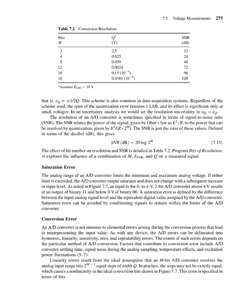
The effect of bit number on resolution and SNR is detailed in Table 7.2. Program Bits of Resolution.
vi explores the influence of a combination of M, E FSR , and Q on a measured signal.
Saturation Error
The analog range of an A/D converter limits the minimum and maximum analog voltage. If either
limit is exceeded, the A/D converter output saturates and does not change with a subsequent increase
in input level. As noted in Figure 7.7, an input to the 0- to 4-V, 2-bit A/D converter above 4 V results
in an output of binary 11 and below 0 V of binary 00. A saturation error is defined by the difference
between the input analog signal level and the equivalent digital value assigned by the A/D converter.
Saturation error can be avoided by conditioning signals to remain within the limits of the A/D
converter.
Conversion Error
An A/D converter is not immune to elemental errors arising during the conversion process that lead
to misrepresenting the input value. As with any device, the A/D errors can be delineated into
hysteresis, linearity, sensitivity, zero, and repeatability errors. The extent of such errors depends on
the particular method of A/D conversion. Factors that contribute to conversion error include A/D
converter settling time, signal noise during the analog sampling, temperature effects, and excitation
power fluctuations (5–7).
Linearity errors result from the ideal assumption that an M-bit A/D converter resolves the
analog input range into 2
M À 1 equal steps of width Q. In practice, the steps may not be exactly equal,
which causes a nonlinearity in the ideal conversion line drawn in Figure 7.7. This error is specified in
terms of bits.
Table 7.2 Conversion Resolution
Bits
Q
a
SNR
M
(V)
(dB)
2
2.5
12
4
0.625
24
8
0.039
48
12
0.0024
72
16
0.15 (10
À3 )
9 6
18
0.0381 (10
À3 )
108
a Assumes E FSR ¼ 10 V.
7.5 Voltage Measurements 275
14:43:49 Page 275
that is, e Q ¼ Æ1/2Q. This scheme is also common in data-acquisition systems. Regardless of the
scheme used, the span of the quantization error remains 1 LSB, and its effect is significant only at
small voltages. In an uncertainty analysis we would set the resolution uncertainty to u Q ¼ e Q .
The resolution of an A/D converter is sometimes specified in terms of signal-to-noise ratio
(SNR). The SNR relates the power of the signal, given by Ohm’s law as E
2
=R, to the power that can
be resolved by quantization, given by E
2 /(RÂ2
M ). The SNR is just the ratio of these values. Defined
in terms of the decibel (dB), this gives
SNR ðdBÞ ¼ 20 log 2
M
ð7:15Þ
The effect of bit number on resolution and SNR is detailed in Table 7.2. Program Bits of Resolution.
vi explores the influence of a combination of M, E FSR , and Q on a measured signal.
Saturation Error
The analog range of an A/D converter limits the minimum and maximum analog voltage. If either
limit is exceeded, the A/D converter output saturates and does not change with a subsequent increase
in input level. As noted in Figure 7.7, an input to the 0- to 4-V, 2-bit A/D converter above 4 V results
in an output of binary 11 and below 0 V of binary 00. A saturation error is defined by the difference
between the input analog signal level and the equivalent digital value assigned by the A/D converter.
Saturation error can be avoided by conditioning signals to remain within the limits of the A/D
converter.
Conversion Error
An A/D converter is not immune to elemental errors arising during the conversion process that lead
to misrepresenting the input value. As with any device, the A/D errors can be delineated into
hysteresis, linearity, sensitivity, zero, and repeatability errors. The extent of such errors depends on
the particular method of A/D conversion. Factors that contribute to conversion error include A/D
converter settling time, signal noise during the analog sampling, temperature effects, and excitation
power fluctuations (5–7).
Linearity errors result from the ideal assumption that an M-bit A/D converter resolves the
analog input range into 2
M À 1 equal steps of width Q. In practice, the steps may not be exactly equal,
which causes a nonlinearity in the ideal conversion line drawn in Figure 7.7. This error is specified in
terms of bits.
Table 7.2 Conversion Resolution
Bits
Q
a
SNR
M
(V)
(dB)
2
2.5
12
4
0.625
24
8
0.039
48
12
0.0024
72
16
0.15 (10
À3 )
9 6
18
0.0381 (10
À3 )
108
a Assumes E FSR ¼ 10 V.
7.5 Voltage Measurements 275