

E1C06 09/14/2010
11:55:7 Page 246
Example 6.9
In a two-speaker (two-way) system, the low-pass circuit passes only low-frequency signal content to
the woofer, while the high-pass circuit passes high-frequency content to the wide-frequency speaker.
The Linkwitz–Riley high-pass or low-pass filter demonstrates a practical use of Butterworth filters
for loudspeaker designs. The 4th order (k ¼ 4) design is a cult standard achieving a 24 dB/octave slope.
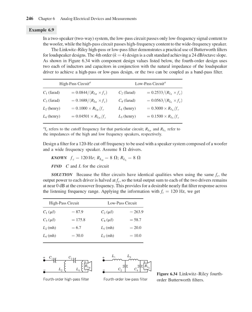
As shown in Figure 6.34 with component design values listed below, the fourth-order design uses
two each of inductors and capacitors in conjunction with the natural impedance of the loudspeaker
driver to achieve a high-pass or low-pass design, or the two can be coupled as a band-pass filter.
High-Pass Circuit
a
Low-Pass Circuit
a
C 1 (farad)
¼ 0:0844=ðR LH Â f c Þ
C 2 (farad)
¼ 0:2533=ðR LL Â f c Þ
C 3 (farad)
¼ 0:1688=ðR LH Â f c Þ
C 4 (farad)
¼ 0:0563=ðR LL Â f c Þ
L 2 (henry)
¼ 0:1000 Â R LH =f c
L 1 (henry)
¼ 0:3000 Â R LL =f c
L 4 (henry)
¼ 0:04501 Â R LH =f c
L 3 (henry)
¼ 0:1500 Â R LL =f c
a f c refers to the cutoff frequency for that particular circuit; R LH and R LL refer to
the impedances of the high and low frequency speakers, respectively.
Design a filter for a 120-Hz cut off frequency to be used with a speaker system composed of a woofer
and a wide frequency speaker. Assume 8 V drivers.
KNOWN f c ¼ 120 Hz; R L H ¼ 8 V; R L L ¼ 8 V
FIND C and L for the circuit
SOLUTION Because the filter circuits have identical qualities when using the same f c , the
output power to each driver is halved at f c , so the total output sum to each of the two drivers remains
at near 0 dB at the crossover frequency. This provides for a desirable nearly flat filter response across
the listening frequency range. Applying the information with f c ¼ 120 Hz, we get
High-Pass Circuit
Low-Pass Circuit
C 1 (mf)
¼ 87.9
C 2 (mf)
¼ 263.9
C 3 (mf)
¼ 175.8
C 4 (mf)
¼ 58.7
L 2 (mh)
¼ 6.7
L 1 (mh)
¼ 20.0
L 4 (mh)
¼ 30.0
L 3 (mh)
¼ 10.0
Fourth-order high-pass filter
+
+
C 1
R L H
L 2
L 4
C 3
–
–
Fourth-order low-pass filter
+
+
L 1
R L L
C 2
C 4
L 3
–
–
Figure 6.34 Linkwitz–Riley fourthorder Butterworth filters.
246 Chapter 6 Analog Electrical Devices and Measurements
11:55:7 Page 246
Example 6.9
In a two-speaker (two-way) system, the low-pass circuit passes only low-frequency signal content to
the woofer, while the high-pass circuit passes high-frequency content to the wide-frequency speaker.
The Linkwitz–Riley high-pass or low-pass filter demonstrates a practical use of Butterworth filters
for loudspeaker designs. The 4th order (k ¼ 4) design is a cult standard achieving a 24 dB/octave slope.
As shown in Figure 6.34 with component design values listed below, the fourth-order design uses
two each of inductors and capacitors in conjunction with the natural impedance of the loudspeaker
driver to achieve a high-pass or low-pass design, or the two can be coupled as a band-pass filter.
High-Pass Circuit
a
Low-Pass Circuit
a
C 1 (farad)
¼ 0:0844=ðR LH Â f c Þ
C 2 (farad)
¼ 0:2533=ðR LL Â f c Þ
C 3 (farad)
¼ 0:1688=ðR LH Â f c Þ
C 4 (farad)
¼ 0:0563=ðR LL Â f c Þ
L 2 (henry)
¼ 0:1000 Â R LH =f c
L 1 (henry)
¼ 0:3000 Â R LL =f c
L 4 (henry)
¼ 0:04501 Â R LH =f c
L 3 (henry)
¼ 0:1500 Â R LL =f c
a f c refers to the cutoff frequency for that particular circuit; R LH and R LL refer to
the impedances of the high and low frequency speakers, respectively.
Design a filter for a 120-Hz cut off frequency to be used with a speaker system composed of a woofer
and a wide frequency speaker. Assume 8 V drivers.
KNOWN f c ¼ 120 Hz; R L H ¼ 8 V; R L L ¼ 8 V
FIND C and L for the circuit
SOLUTION Because the filter circuits have identical qualities when using the same f c , the
output power to each driver is halved at f c , so the total output sum to each of the two drivers remains
at near 0 dB at the crossover frequency. This provides for a desirable nearly flat filter response across
the listening frequency range. Applying the information with f c ¼ 120 Hz, we get
High-Pass Circuit
Low-Pass Circuit
C 1 (mf)
¼ 87.9
C 2 (mf)
¼ 263.9
C 3 (mf)
¼ 175.8
C 4 (mf)
¼ 58.7
L 2 (mh)
¼ 6.7
L 1 (mh)
¼ 20.0
L 4 (mh)
¼ 30.0
L 3 (mh)
¼ 10.0
Fourth-order high-pass filter
+
+
C 1
R L H
L 2
L 4
C 3
–
–
Fourth-order low-pass filter
+
+
L 1
R L L
C 2
C 4
L 3
–
–
Figure 6.34 Linkwitz–Riley fourthorder Butterworth filters.
246 Chapter 6 Analog Electrical Devices and Measurements