

E1C06 09/14/2010
11:55:7 Page 247
Commercial values for each element that are close to these calculated would be used in the circuit of
Figure 6.34 to achieve a cutoff as close to 120 Hz as possible.
Bessel Filter Design
A Bessel filter will sacrifice a flat gain over its passband with a gradual initial roll-off in order to
maximize a linear phase response over portions of the passband. A linear phase response closely
resembles a time delay, reducing distortion. Thus, the attractiveness of a Bessel filter is the ability to
pass wideband signals with a minimum of distortion. The filter is widely used for different
applications, including audio design where crossover phase shift can have an effect on sound quality.
A k-stage low-pass Bessel filter has the transfer function
KG s
ð Þ ¼
a o
a o þ a 1 s þ Á Á Á þ a k s k
ð6:64Þ
For design purposes, this can be rewritten as
KG s
ð Þ ¼
a o
D k s
ð Þ
ð6:65Þ
where D k s
ð Þ ¼ 2k À 1
ð
ÞD kÀ1 s
ð Þ þ s
2
D kÀ2 s
ð Þ; D o s
ð Þ ¼ 1 and D 1 (s) ¼ s þ 1.
A k-stage LC low-pass Bessel filter can be designed based on the filter circuit shown in Figure
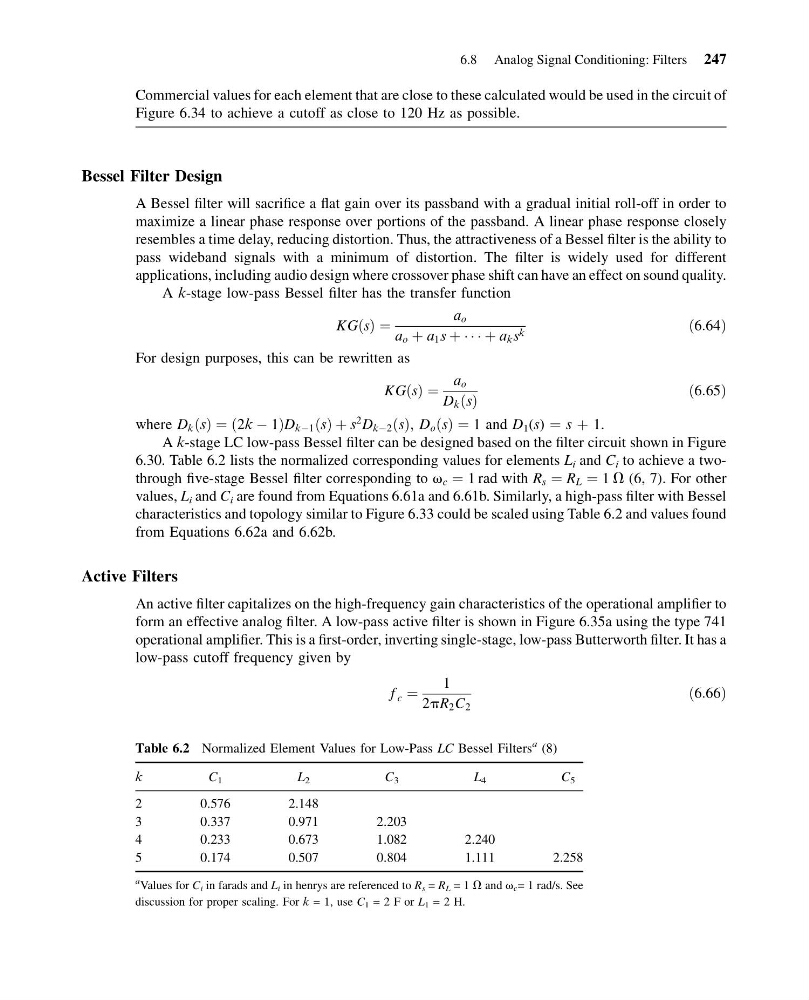
6.30. Table 6.2 lists the normalized corresponding values for elements L i and C i to achieve a twothrough five-stage Bessel filter corresponding to v c ¼ 1 rad with R s ¼ R L ¼ 1 V (6, 7). For other
values, L i and C i are found from Equations 6.61a and 6.61b. Similarly, a high-pass filter with Bessel
characteristics and topology similar to Figure 6.33 could be scaled using Table 6.2 and values found
from Equations 6.62a and 6.62b.
Active Filters
An active filter capitalizes on the high-frequency gain characteristics of the operational amplifier to
form an effective analog filter. A low-pass active filter is shown in Figure 6.35a using the type 741
operational amplifier. This is a first-order, inverting single-stage, low-pass Butterworth filter. It has a
low-pass cutoff frequency given by
f c ¼
1
2pR 2 C 2
ð6:66Þ
Table 6.2 Normalized Element Values for Low-Pass LC Bessel Filters
a (8)
k
C 1
L 2
C 3
L 4
C 5
2
0.576
2.148
3
0.337
0.971
2.203
4
0.233
0.673
1.082
2.240
5
0.174
0.507
0.804
1.111
2.258
a Values for C i in farads and L i in henrys are referenced to R s = R L = 1 V and v c = 1 rad/s. See
discussion for proper scaling. For k = 1, use C 1 = 2 F or L 1 = 2 H.
6.8 Analog Signal Conditioning: Filters 247
11:55:7 Page 247
Commercial values for each element that are close to these calculated would be used in the circuit of
Figure 6.34 to achieve a cutoff as close to 120 Hz as possible.
Bessel Filter Design
A Bessel filter will sacrifice a flat gain over its passband with a gradual initial roll-off in order to
maximize a linear phase response over portions of the passband. A linear phase response closely
resembles a time delay, reducing distortion. Thus, the attractiveness of a Bessel filter is the ability to
pass wideband signals with a minimum of distortion. The filter is widely used for different
applications, including audio design where crossover phase shift can have an effect on sound quality.
A k-stage low-pass Bessel filter has the transfer function
KG s
ð Þ ¼
a o
a o þ a 1 s þ Á Á Á þ a k s k
ð6:64Þ
For design purposes, this can be rewritten as
KG s
ð Þ ¼
a o
D k s
ð Þ
ð6:65Þ
where D k s
ð Þ ¼ 2k À 1
ð
ÞD kÀ1 s
ð Þ þ s
2
D kÀ2 s
ð Þ; D o s
ð Þ ¼ 1 and D 1 (s) ¼ s þ 1.
A k-stage LC low-pass Bessel filter can be designed based on the filter circuit shown in Figure
6.30. Table 6.2 lists the normalized corresponding values for elements L i and C i to achieve a twothrough five-stage Bessel filter corresponding to v c ¼ 1 rad with R s ¼ R L ¼ 1 V (6, 7). For other
values, L i and C i are found from Equations 6.61a and 6.61b. Similarly, a high-pass filter with Bessel
characteristics and topology similar to Figure 6.33 could be scaled using Table 6.2 and values found
from Equations 6.62a and 6.62b.
Active Filters
An active filter capitalizes on the high-frequency gain characteristics of the operational amplifier to
form an effective analog filter. A low-pass active filter is shown in Figure 6.35a using the type 741
operational amplifier. This is a first-order, inverting single-stage, low-pass Butterworth filter. It has a
low-pass cutoff frequency given by
f c ¼
1
2pR 2 C 2
ð6:66Þ
Table 6.2 Normalized Element Values for Low-Pass LC Bessel Filters
a (8)
k
C 1
L 2
C 3
L 4
C 5
2
0.576
2.148
3
0.337
0.971
2.203
4
0.233
0.673
1.082
2.240
5
0.174
0.507
0.804
1.111
2.258
a Values for C i in farads and L i in henrys are referenced to R s = R L = 1 V and v c = 1 rad/s. See
discussion for proper scaling. For k = 1, use C 1 = 2 F or L 1 = 2 H.
6.8 Analog Signal Conditioning: Filters 247