

E1C06 09/14/2010
11:55:7 Page 245
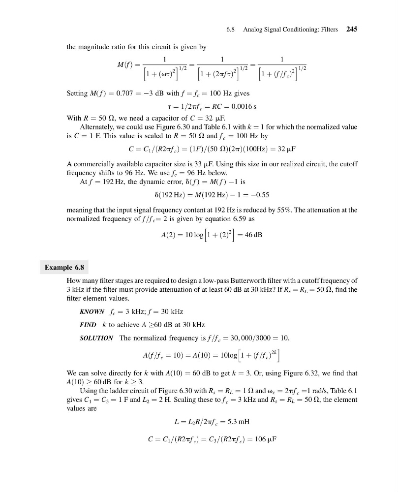
the magnitude ratio for this circuit is given by
M f
ð Þ ¼
1
1 þ vt
ð Þ
2
h
i 1=2 ¼
1
1 þ 2pf t
ð
Þ
2
h
i 1=2 ¼
1
1 þ f =f c
ð
Þ
2
h
i 1=2
Setting M( f ) ¼ 0.707 ¼ À3 dB with f ¼ f c ¼ 100 Hz gives
t ¼ 1=2pf c ¼ RC ¼ 0:0016 s
With R ¼ 50 V, we need a capacitor of C ¼ 32 mF.
Alternately, we could use Figure 6.30 and Table 6.1 with k ¼ 1 for which the normalized value
is C ¼ 1 F. This value is scaled to R ¼ 50 V and f c ¼ 100 Hz by
C ¼ C 1 = R2pf c
ð
Þ¼ð1FÞ=ð50 VÞð2pÞð100HzÞ ¼ 32 mF
A commercially available capacitor size is 33 mF. Using this size in our realized circuit, the cutoff
frequency shifts to 96 Hz. We use f c ¼ 96 Hz below.
At f ¼ 192 Hz, the dynamic error, d( f ) ¼ M( f ) À1 is
d 192 Hz
ð
Þ¼M 192 Hz
ð
ÞÀ1 ¼ À0:55
meaning that the input signal frequency content at 192 Hz is reduced by 55%. The attenuation at the
normalized frequency of f =f c ¼ 2 is given by equation 6.59 as
Að2Þ ¼ 10 log 1 þ 2
ð Þ
2
h
i
¼ 46 dB
Example 6.8
How many filter stages are required to design a low-pass Butterworth filter with a cutoff frequency of
3 kHz if the filter must provide attenuation of at least 60 dB at 30 kHz? If R s ¼ R L ¼ 50 V, find the
filter element values.
KNOWN f c ¼ 3 kHz; f ¼ 30 kHz
FIND k to achieve A !60 dB at 30 kHz
SOLUTION The normalized frequency is f =f c ¼ 30; 000=3000 ¼ 10.
Aðf =f c ¼ 10Þ ¼ Að10Þ ¼ 10log 1 þ ðf =f c Þ
2k
h
i
We can solve directly for k with A(10) ¼ 60 dB to get k ¼ 3. Or, using Figure 6.32, we find that
Að10Þ ! 60 dB for k ! 3.
Using the ladder circuit of Figure 6.30 with R s ¼ R L ¼ 1 V and v c ¼ 2pf c ¼1 rad/s, Table 6.1
gives C 1 ¼ C 3 ¼ 1 F and L 2 ¼ 2 H. Scaling these to f c ¼ 3 kHz and R s ¼ R L ¼ 50 V, the element
values are
L ¼ L 2 R=2pf c ¼ 5:3 mH
C ¼ C 1 = R2pf c
ð
Þ¼C 3 = R2pf c
ð
Þ¼106 mF
6.8 Analog Signal Conditioning: Filters 245
11:55:7 Page 245
the magnitude ratio for this circuit is given by
M f
ð Þ ¼
1
1 þ vt
ð Þ
2
h
i 1=2 ¼
1
1 þ 2pf t
ð
Þ
2
h
i 1=2 ¼
1
1 þ f =f c
ð
Þ
2
h
i 1=2
Setting M( f ) ¼ 0.707 ¼ À3 dB with f ¼ f c ¼ 100 Hz gives
t ¼ 1=2pf c ¼ RC ¼ 0:0016 s
With R ¼ 50 V, we need a capacitor of C ¼ 32 mF.
Alternately, we could use Figure 6.30 and Table 6.1 with k ¼ 1 for which the normalized value
is C ¼ 1 F. This value is scaled to R ¼ 50 V and f c ¼ 100 Hz by
C ¼ C 1 = R2pf c
ð
Þ¼ð1FÞ=ð50 VÞð2pÞð100HzÞ ¼ 32 mF
A commercially available capacitor size is 33 mF. Using this size in our realized circuit, the cutoff
frequency shifts to 96 Hz. We use f c ¼ 96 Hz below.
At f ¼ 192 Hz, the dynamic error, d( f ) ¼ M( f ) À1 is
d 192 Hz
ð
Þ¼M 192 Hz
ð
ÞÀ1 ¼ À0:55
meaning that the input signal frequency content at 192 Hz is reduced by 55%. The attenuation at the
normalized frequency of f =f c ¼ 2 is given by equation 6.59 as
Að2Þ ¼ 10 log 1 þ 2
ð Þ
2
h
i
¼ 46 dB
Example 6.8
How many filter stages are required to design a low-pass Butterworth filter with a cutoff frequency of
3 kHz if the filter must provide attenuation of at least 60 dB at 30 kHz? If R s ¼ R L ¼ 50 V, find the
filter element values.
KNOWN f c ¼ 3 kHz; f ¼ 30 kHz
FIND k to achieve A !60 dB at 30 kHz
SOLUTION The normalized frequency is f =f c ¼ 30; 000=3000 ¼ 10.
Aðf =f c ¼ 10Þ ¼ Að10Þ ¼ 10log 1 þ ðf =f c Þ
2k
h
i
We can solve directly for k with A(10) ¼ 60 dB to get k ¼ 3. Or, using Figure 6.32, we find that
Að10Þ ! 60 dB for k ! 3.
Using the ladder circuit of Figure 6.30 with R s ¼ R L ¼ 1 V and v c ¼ 2pf c ¼1 rad/s, Table 6.1
gives C 1 ¼ C 3 ¼ 1 F and L 2 ¼ 2 H. Scaling these to f c ¼ 3 kHz and R s ¼ R L ¼ 50 V, the element
values are
L ¼ L 2 R=2pf c ¼ 5:3 mH
C ¼ C 1 = R2pf c
ð
Þ¼C 3 = R2pf c
ð
Þ¼106 mF
6.8 Analog Signal Conditioning: Filters 245