

E1C06 09/14/2010
11:55:6 Page 243
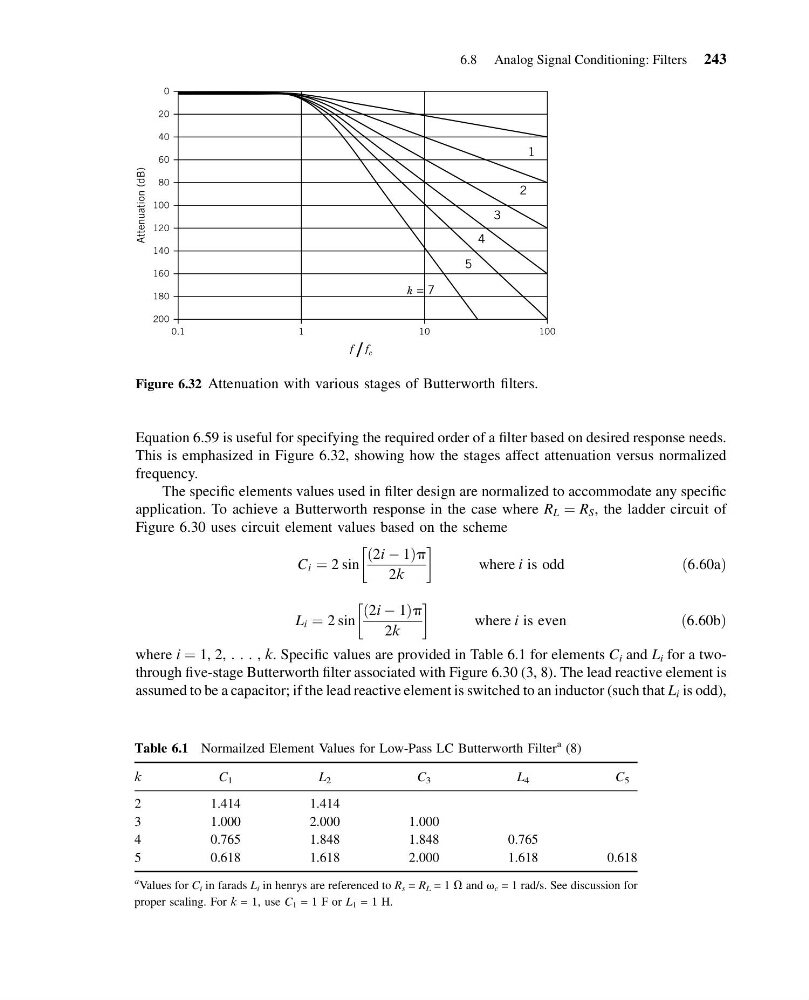
Equation 6.59 is useful for specifying the required order of a filter based on desired response needs.
This is emphasized in Figure 6.32, showing how the stages affect attenuation versus normalized
frequency.
The specific elements values used in filter design are normalized to accommodate any specific
application. To achieve a Butterworth response in the case where R L ¼ R S , the ladder circuit of
Figure 6.30 uses circuit element values based on the scheme
C i ¼ 2 sin
2i À 1
ð
Þp
2k
!
where i is odd
ð6:60aÞ
L i ¼ 2 sin
2i À 1
ð
Þp
2k
!
where i is even
ð6:60bÞ
where i ¼ 1, 2, . . . , k. Specific values are provided in Table 6.1 for elements C i and L i for a twothrough five-stage Butterworth filter associated with Figure 6.30 (3, 8). The lead reactive element is
assumed to be a capacitor; if the lead reactive element is switched to an inductor (such that L i is odd),
0
20
40
60
80
100
120
140
160
180
200
0.1
1
k = 7
5
4
3
2
1
Attenuation (dB)
10
100
f / f c
Figure 6.32 Attenuation with various stages of Butterworth filters.
Table 6.1 Normailzed Element Values for Low-Pass LC Butterworth Filter
a (8)
k
C 1
L 2
C 3
L 4
C 5
2
1.414
1.414
3
1.000
2.000
1.000
4
0.765
1.848
1.848
0.765
5
0.618
1.618
2.000
1.618
0.618
a Values for C i in farads L i in henrys are referenced to R s = R L = 1 V and v c = 1 rad/s. See discussion for
proper scaling. For k = 1, use C 1 = 1 F or L 1 = 1 H.
6.8 Analog Signal Conditioning: Filters 243
11:55:6 Page 243
Equation 6.59 is useful for specifying the required order of a filter based on desired response needs.
This is emphasized in Figure 6.32, showing how the stages affect attenuation versus normalized
frequency.
The specific elements values used in filter design are normalized to accommodate any specific
application. To achieve a Butterworth response in the case where R L ¼ R S , the ladder circuit of
Figure 6.30 uses circuit element values based on the scheme
C i ¼ 2 sin
2i À 1
ð
Þp
2k
!
where i is odd
ð6:60aÞ
L i ¼ 2 sin
2i À 1
ð
Þp
2k
!
where i is even
ð6:60bÞ
where i ¼ 1, 2, . . . , k. Specific values are provided in Table 6.1 for elements C i and L i for a twothrough five-stage Butterworth filter associated with Figure 6.30 (3, 8). The lead reactive element is
assumed to be a capacitor; if the lead reactive element is switched to an inductor (such that L i is odd),
0
20
40
60
80
100
120
140
160
180
200
0.1
1
k = 7
5
4
3
2
1
Attenuation (dB)
10
100
f / f c
Figure 6.32 Attenuation with various stages of Butterworth filters.
Table 6.1 Normailzed Element Values for Low-Pass LC Butterworth Filter
a (8)
k
C 1
L 2
C 3
L 4
C 5
2
1.414
1.414
3
1.000
2.000
1.000
4
0.765
1.848
1.848
0.765
5
0.618
1.618
2.000
1.618
0.618
a Values for C i in farads L i in henrys are referenced to R s = R L = 1 V and v c = 1 rad/s. See discussion for
proper scaling. For k = 1, use C 1 = 1 F or L 1 = 1 H.
6.8 Analog Signal Conditioning: Filters 243