

E1C06 09/14/2010
11:55:6 Page 242
resulting LC ladder circuit of Figure 6.30. The resistances R s and R L refer to the circuit source and
load impedances, respectively. A kth-order or k-stage filter contains k reactive elements in stages.
The magnitude ratio and phase shift for a k-stage low-pass Butterworth filter are given by
M f
ð Þ ¼
1
1 þ f =f c
ð
Þ
2k
h
i 1=2
ð6:58aÞ
F f
ð Þ ¼
X k
i¼1
F i k
ð Þ
ð6:58bÞ
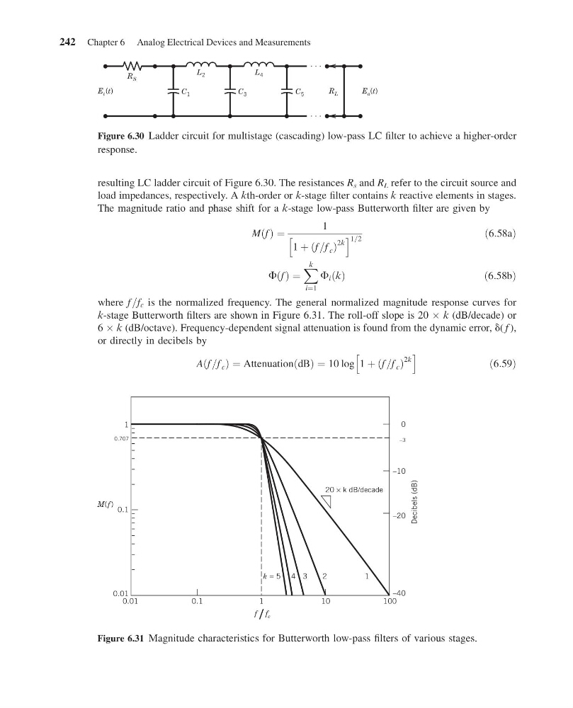
where f =f c is the normalized frequency. The general normalized magnitude response curves for
k-stage Butterworth filters are shown in Figure 6.31. The roll-off slope is 20 Â k (dB/decade) or
6 Â k (dB/octave). Frequency-dependent signal attenuation is found from the dynamic error, d( f ),
or directly in decibels by
Aðf =f c Þ ¼ Attenuation dB
ð Þ ¼ 10 log 1 þ f =f c
ð
Þ
2k
h
i
ð6:59Þ
L 2
L 4
C 1
C 3
C 5
E i (t)
E o (t)
R L
R S
Figure 6.30 Ladder circuit for multistage (cascading) low-pass LC filter to achieve a higher-order
response.
0.1
0.01
f / f c
0.1
0.707
0.01
1
M( f )
1
10
20 × k dB/decade
1
2
3
4
k = 5
100
Decibels (dB)
–40
–20
–10
–3
0
Figure 6.31 Magnitude characteristics for Butterworth low-pass filters of various stages.
242 Chapter 6 Analog Electrical Devices and Measurements
11:55:6 Page 242
resulting LC ladder circuit of Figure 6.30. The resistances R s and R L refer to the circuit source and
load impedances, respectively. A kth-order or k-stage filter contains k reactive elements in stages.
The magnitude ratio and phase shift for a k-stage low-pass Butterworth filter are given by
M f
ð Þ ¼
1
1 þ f =f c
ð
Þ
2k
h
i 1=2
ð6:58aÞ
F f
ð Þ ¼
X k
i¼1
F i k
ð Þ
ð6:58bÞ
where f =f c is the normalized frequency. The general normalized magnitude response curves for
k-stage Butterworth filters are shown in Figure 6.31. The roll-off slope is 20 Â k (dB/decade) or
6 Â k (dB/octave). Frequency-dependent signal attenuation is found from the dynamic error, d( f ),
or directly in decibels by
Aðf =f c Þ ¼ Attenuation dB
ð Þ ¼ 10 log 1 þ f =f c
ð
Þ
2k
h
i
ð6:59Þ
L 2
L 4
C 1
C 3
C 5
E i (t)
E o (t)
R L
R S
Figure 6.30 Ladder circuit for multistage (cascading) low-pass LC filter to achieve a higher-order
response.
0.1
0.01
f / f c
0.1
0.707
0.01
1
M( f )
1
10
20 × k dB/decade
1
2
3
4
k = 5
100
Decibels (dB)
–40
–20
–10
–3
0
Figure 6.31 Magnitude characteristics for Butterworth low-pass filters of various stages.
242 Chapter 6 Analog Electrical Devices and Measurements