

E1C06 09/14/2010
11:55:6 Page 241
passband to the stopband. This rate of transition is known as the filter roll-off, usually specified in
units of dB/decade. In addition, the filter introduces a phase shift between its input and output signal.
The design of real filters is focused on certain desirable response features. The magnitude and phase
characteristics of a real filter can be optimized to meet one of the following: (1) maximum
magnitude flatness over the passband, (2) a linear phase response over the passband, or (3) a sharp
transition from the passband to stopband with steep roll-off. No one filter can meet all three,
characteristics but we can design for any one of them. For example, a relatively flat magnitude ratio
over its passband with a moderately steep initial roll-off and acceptable phase response is a
characteristic of a Butterworth filter response. On the other hand, a very linear phase shift over its
passband but with a relatively gradual initial roll-off is a characteristic of a Bessel filter response.
The frequency-dependent behavior of low-pass, bandpass, and high-pass filters can be explored in
the LabView programs Butterworth filters and Bessel filters.
Butterworth Filter Design
A Butterworth filter is optimized to achieve maximum flatness in magnitude ratio over the passband.
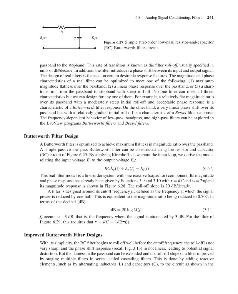
A simple passive low-pass Butterworth filter can be constructed using the resistor-and-capacitor
(RC) circuit of Figure 6.29. By applying Kirchhoff’s law about the input loop, we derive the model
relating the input voltage E i to the output voltage E o :
RC _
E o t
ð Þ þ E o t
ð Þ ¼ E i t
ð Þ
ð6:57Þ
This real filter model is a first-order system with one reactive (capacitor) component. Its magnitude
and phase response has already been given by Equations 3.9 and 3.10 with t ¼ RC and v ¼ 2pf and
its magnitude response is shown in Figure 6.28. The roll-off slope is 20 dB/decade.
A filter is designed around its cutoff frequency f c , defined as the frequency at which the signal
power is reduced by one-half. This is equivalent to the magnitude ratio being reduced to 0.707. In
terms of the decibel (dB),
dB ¼ 20 log M f
ð Þ
ð3:11Þ
f c occurs at À3 dB, that is, the frequency where the signal is attenuated by 3 dB. For the filter of
Figure 6.29, this requires that t ¼ RC ¼ 1/(2pf c ).
Improved Butterworth Filter Designs
With its simplicity, the RC filter begins to roll off well before the cutoff frequency; the roll-off is not
very sharp, and the phase shift response (recall Fig. 3.13) in not linear, leading to potential signal
distortion. But the flatness in the passband can be extended and the roll-off slope of a filter improved
by staging multiple filters in series, called cascading filters. This is done by adding reactive
elements, such as by alternating inductors (L) and capacitors (C), to the circuit as shown in the
R
C
E i (t)
E o (t)
Figure 6.29 Simple first-order low-pass resistor-and-capacitor
(RC) Butterworth filter circuit.
6.8 Analog Signal Conditioning: Filters 241
11:55:6 Page 241
passband to the stopband. This rate of transition is known as the filter roll-off, usually specified in
units of dB/decade. In addition, the filter introduces a phase shift between its input and output signal.
The design of real filters is focused on certain desirable response features. The magnitude and phase
characteristics of a real filter can be optimized to meet one of the following: (1) maximum
magnitude flatness over the passband, (2) a linear phase response over the passband, or (3) a sharp
transition from the passband to stopband with steep roll-off. No one filter can meet all three,
characteristics but we can design for any one of them. For example, a relatively flat magnitude ratio
over its passband with a moderately steep initial roll-off and acceptable phase response is a
characteristic of a Butterworth filter response. On the other hand, a very linear phase shift over its
passband but with a relatively gradual initial roll-off is a characteristic of a Bessel filter response.
The frequency-dependent behavior of low-pass, bandpass, and high-pass filters can be explored in
the LabView programs Butterworth filters and Bessel filters.
Butterworth Filter Design
A Butterworth filter is optimized to achieve maximum flatness in magnitude ratio over the passband.
A simple passive low-pass Butterworth filter can be constructed using the resistor-and-capacitor
(RC) circuit of Figure 6.29. By applying Kirchhoff’s law about the input loop, we derive the model
relating the input voltage E i to the output voltage E o :
RC _
E o t
ð Þ þ E o t
ð Þ ¼ E i t
ð Þ
ð6:57Þ
This real filter model is a first-order system with one reactive (capacitor) component. Its magnitude
and phase response has already been given by Equations 3.9 and 3.10 with t ¼ RC and v ¼ 2pf and
its magnitude response is shown in Figure 6.28. The roll-off slope is 20 dB/decade.
A filter is designed around its cutoff frequency f c , defined as the frequency at which the signal
power is reduced by one-half. This is equivalent to the magnitude ratio being reduced to 0.707. In
terms of the decibel (dB),
dB ¼ 20 log M f
ð Þ
ð3:11Þ
f c occurs at À3 dB, that is, the frequency where the signal is attenuated by 3 dB. For the filter of
Figure 6.29, this requires that t ¼ RC ¼ 1/(2pf c ).
Improved Butterworth Filter Designs
With its simplicity, the RC filter begins to roll off well before the cutoff frequency; the roll-off is not
very sharp, and the phase shift response (recall Fig. 3.13) in not linear, leading to potential signal
distortion. But the flatness in the passband can be extended and the roll-off slope of a filter improved
by staging multiple filters in series, called cascading filters. This is done by adding reactive
elements, such as by alternating inductors (L) and capacitors (C), to the circuit as shown in the
R
C
E i (t)
E o (t)
Figure 6.29 Simple first-order low-pass resistor-and-capacitor
(RC) Butterworth filter circuit.
6.8 Analog Signal Conditioning: Filters 241