

E1C06 09/14/2010
11:55:6 Page 238
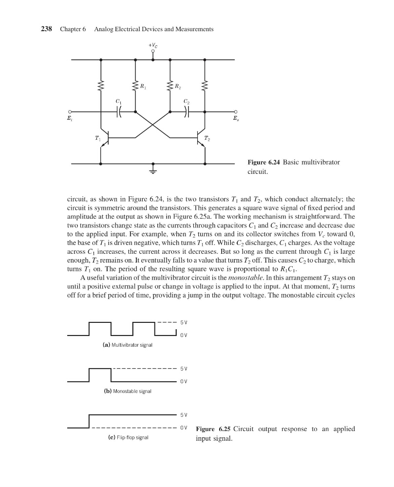
circuit, as shown in Figure 6.24, is the two transistors T 1 and T 2 , which conduct alternately; the
circuit is symmetric around the transistors. This generates a square wave signal of fixed period and
amplitude at the output as shown in Figure 6.25a. The working mechanism is straightforward. The
two transistors change state as the currents through capacitors C 1 and C 2 increase and decrease due
to the applied input. For example, when T 2 turns on and its collector switches from V c toward 0,
the base of T 1 is driven negative, which turns T 1 off. While C 2 discharges, C 1 charges. As the voltage
across C 1 increases, the current across it decreases. But so long as the current through C 1 is large
enough, T 2 remains on. It eventually falls to a value that turns T 2 off. This causes C 2 to charge, which
turns T 1 on. The period of the resulting square wave is proportional to R 1 C 1 .
A useful variation of the multivibrator circuit is the monostable. In this arrangement T 2 stays on
until a positive external pulse or change in voltage is applied to the input. At that moment, T 2 turns
off for a brief period of time, providing a jump in the output voltage. The monostable circuit cycles
+V c
E i
E o
T 2
T 1
C 1
C 2
R 1
R 2
Figure 6.24 Basic multivibrator
circuit.
(a) Multivibrator signal
5 V
0 V
5 V
0 V
5 V
0 V
(b) Monostable signal
(c) Flip-flop signal
Figure 6.25 Circuit output response to an applied
input signal.
238 Chapter 6 Analog Electrical Devices and Measurements
11:55:6 Page 238
circuit, as shown in Figure 6.24, is the two transistors T 1 and T 2 , which conduct alternately; the
circuit is symmetric around the transistors. This generates a square wave signal of fixed period and
amplitude at the output as shown in Figure 6.25a. The working mechanism is straightforward. The
two transistors change state as the currents through capacitors C 1 and C 2 increase and decrease due
to the applied input. For example, when T 2 turns on and its collector switches from V c toward 0,
the base of T 1 is driven negative, which turns T 1 off. While C 2 discharges, C 1 charges. As the voltage
across C 1 increases, the current across it decreases. But so long as the current through C 1 is large
enough, T 2 remains on. It eventually falls to a value that turns T 2 off. This causes C 2 to charge, which
turns T 1 on. The period of the resulting square wave is proportional to R 1 C 1 .
A useful variation of the multivibrator circuit is the monostable. In this arrangement T 2 stays on
until a positive external pulse or change in voltage is applied to the input. At that moment, T 2 turns
off for a brief period of time, providing a jump in the output voltage. The monostable circuit cycles
+V c
E i
E o
T 2
T 1
C 1
C 2
R 1
R 2
Figure 6.24 Basic multivibrator
circuit.
(a) Multivibrator signal
5 V
0 V
5 V
0 V
5 V
0 V
(b) Monostable signal
(c) Flip-flop signal
Figure 6.25 Circuit output response to an applied
input signal.
238 Chapter 6 Analog Electrical Devices and Measurements