

E1C06 09/14/2010
11:55:6 Page 239
just once, awaiting another pulse as shown in Figure 6.25b. Hence, it is often referred to as a oneshot. Because it fires just once and resets itself, the monostable is an effective trigger.
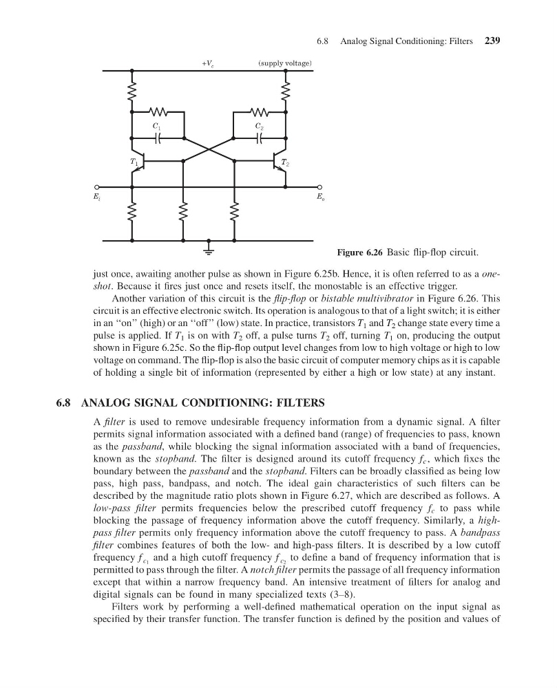
Another variation of this circuit is the flip-flop or bistable multivibrator in Figure 6.26. This
circuit is an effective electronic switch. Its operation is analogous to that of a light switch; it is either
in an ‘‘on’’ (high) or an ‘‘off’’ (low) state. In practice, transistors T 1 and T 2 change state every time a
pulse is applied. If T 1 is on with T 2 off, a pulse turns T 2 off, turning T 1 on, producing the output
shown in Figure 6.25c. So the flip-flop output level changes from low to high voltage or high to low
voltage on command. The flip-flop is also the basic circuit of computer memory chips as it is capable
of holding a single bit of information (represented by either a high or low state) at any instant.
6.8 ANALOG SIGNAL CONDITIONING: FILTERS
A filter is used to remove undesirable frequency information from a dynamic signal. A filter
permits signal information associated with a defined band (range) of frequencies to pass, known
as the passband, while blocking the signal information associated with a band of frequencies,
known as the stopband. The filter is designed around its cutoff frequency f c , which fixes the
boundary between the passband and the stopband. Filters can be broadly classified as being low
pass, high pass, bandpass, and notch. The ideal gain characteristics of such filters can be
described by the magnitude ratio plots shown in Figure 6.27, which are described as follows. A
low-pass filter permits frequencies below the prescribed cutoff frequency f c to pass while
blocking the passage of frequency information above the cutoff frequency. Similarly, a highpass filter permits only frequency information above the cutoff frequency to pass. A bandpass
filter combines features of both the low- and high-pass filters. It is described by a low cutoff
frequency f c 1 and a high cutoff frequency f c 2 to define a band of frequency information that is
permitted to pass through the filter. A notch filter permits the passage of all frequency information
except that within a narrow frequency band. An intensive treatment of filters for analog and
digital signals can be found in many specialized texts (3–8).
Filters work by performing a well-defined mathematical operation on the input signal as
specified by their transfer function. The transfer function is defined by the position and values of
E i
C 1
T 1
C 2
T 2
E o
+V
(supply voltage)
c
Figure 6.26 Basic flip-flop circuit.
6.8 Analog Signal Conditioning: Filters 239
11:55:6 Page 239
just once, awaiting another pulse as shown in Figure 6.25b. Hence, it is often referred to as a oneshot. Because it fires just once and resets itself, the monostable is an effective trigger.
Another variation of this circuit is the flip-flop or bistable multivibrator in Figure 6.26. This
circuit is an effective electronic switch. Its operation is analogous to that of a light switch; it is either
in an ‘‘on’’ (high) or an ‘‘off’’ (low) state. In practice, transistors T 1 and T 2 change state every time a
pulse is applied. If T 1 is on with T 2 off, a pulse turns T 2 off, turning T 1 on, producing the output
shown in Figure 6.25c. So the flip-flop output level changes from low to high voltage or high to low
voltage on command. The flip-flop is also the basic circuit of computer memory chips as it is capable
of holding a single bit of information (represented by either a high or low state) at any instant.
6.8 ANALOG SIGNAL CONDITIONING: FILTERS
A filter is used to remove undesirable frequency information from a dynamic signal. A filter
permits signal information associated with a defined band (range) of frequencies to pass, known
as the passband, while blocking the signal information associated with a band of frequencies,
known as the stopband. The filter is designed around its cutoff frequency f c , which fixes the
boundary between the passband and the stopband. Filters can be broadly classified as being low
pass, high pass, bandpass, and notch. The ideal gain characteristics of such filters can be
described by the magnitude ratio plots shown in Figure 6.27, which are described as follows. A
low-pass filter permits frequencies below the prescribed cutoff frequency f c to pass while
blocking the passage of frequency information above the cutoff frequency. Similarly, a highpass filter permits only frequency information above the cutoff frequency to pass. A bandpass
filter combines features of both the low- and high-pass filters. It is described by a low cutoff
frequency f c 1 and a high cutoff frequency f c 2 to define a band of frequency information that is
permitted to pass through the filter. A notch filter permits the passage of all frequency information
except that within a narrow frequency band. An intensive treatment of filters for analog and
digital signals can be found in many specialized texts (3–8).
Filters work by performing a well-defined mathematical operation on the input signal as
specified by their transfer function. The transfer function is defined by the position and values of
E i
C 1
T 1
C 2
T 2
E o
+V
(supply voltage)
c
Figure 6.26 Basic flip-flop circuit.
6.8 Analog Signal Conditioning: Filters 239