

E1C06 09/14/2010
11:55:6 Page 237
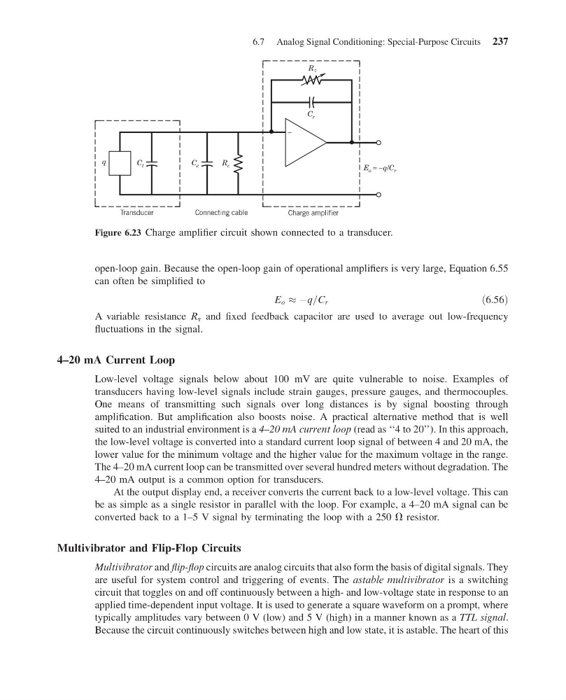
open-loop gain. Because the open-loop gain of operational amplifiers is very large, Equation 6.55
can often be simplified to
E o % Àq=C r
ð6:56Þ
A variable resistance R t and fixed feedback capacitor are used to average out low-frequency
fluctuations in the signal.
4–20 mA Current Loop
Low-level voltage signals below about 100 mV are quite vulnerable to noise. Examples of
transducers having low-level signals include strain gauges, pressure gauges, and thermocouples.
One means of transmitting such signals over long distances is by signal boosting through
amplification. But amplification also boosts noise. A practical alternative method that is well
suited to an industrial environment is a 4–20 mA current loop (read as ‘‘4 to 20’’). In this approach,
the low-level voltage is converted into a standard current loop signal of between 4 and 20 mA, the
lower value for the minimum voltage and the higher value for the maximum voltage in the range.
The 4–20 mA current loop can be transmitted over several hundred meters without degradation. The
4–20 mA output is a common option for transducers.
At the output display end, a receiver converts the current back to a low-level voltage. This can
be as simple as a single resistor in parallel with the loop. For example, a 4–20 mA signal can be
converted back to a 1–5 V signal by terminating the loop with a 250 V resistor.
Multivibrator and Flip-Flop Circuits
Multivibrator and flip-flop circuits are analog circuits that also form the basis of digital signals. They
are useful for system control and triggering of events. The astable multivibrator is a switching
circuit that toggles on and off continuously between a high- and low-voltage state in response to an
applied time-dependent input voltage. It is used to generate a square waveform on a prompt, where
typically amplitudes vary between 0 V (low) and 5 V (high) in a manner known as a TTL signal.
Because the circuit continuously switches between high and low state, it is astable. The heart of this
q
C t
C c
R c
C r
E o ≈ –q/C r
Transducer
Connecting cable
Charge amplifier
–
R τ
Figure 6.23 Charge amplifier circuit shown connected to a transducer.
6.7 Analog Signal Conditioning: Special-Purpose Circuits 237
11:55:6 Page 237
open-loop gain. Because the open-loop gain of operational amplifiers is very large, Equation 6.55
can often be simplified to
E o % Àq=C r
ð6:56Þ
A variable resistance R t and fixed feedback capacitor are used to average out low-frequency
fluctuations in the signal.
4–20 mA Current Loop
Low-level voltage signals below about 100 mV are quite vulnerable to noise. Examples of
transducers having low-level signals include strain gauges, pressure gauges, and thermocouples.
One means of transmitting such signals over long distances is by signal boosting through
amplification. But amplification also boosts noise. A practical alternative method that is well
suited to an industrial environment is a 4–20 mA current loop (read as ‘‘4 to 20’’). In this approach,
the low-level voltage is converted into a standard current loop signal of between 4 and 20 mA, the
lower value for the minimum voltage and the higher value for the maximum voltage in the range.
The 4–20 mA current loop can be transmitted over several hundred meters without degradation. The
4–20 mA output is a common option for transducers.
At the output display end, a receiver converts the current back to a low-level voltage. This can
be as simple as a single resistor in parallel with the loop. For example, a 4–20 mA signal can be
converted back to a 1–5 V signal by terminating the loop with a 250 V resistor.
Multivibrator and Flip-Flop Circuits
Multivibrator and flip-flop circuits are analog circuits that also form the basis of digital signals. They
are useful for system control and triggering of events. The astable multivibrator is a switching
circuit that toggles on and off continuously between a high- and low-voltage state in response to an
applied time-dependent input voltage. It is used to generate a square waveform on a prompt, where
typically amplitudes vary between 0 V (low) and 5 V (high) in a manner known as a TTL signal.
Because the circuit continuously switches between high and low state, it is astable. The heart of this
q
C t
C c
R c
C r
E o ≈ –q/C r
Transducer
Connecting cable
Charge amplifier
–
R τ
Figure 6.23 Charge amplifier circuit shown connected to a transducer.
6.7 Analog Signal Conditioning: Special-Purpose Circuits 237