

E1C06 09/14/2010
11:55:6 Page 236
Charge Amplifier
A charge amplifier is used to convert a high-impedance charge q into an output voltage E o . The
circuit consists of a high-gain, inverting voltage operational amplifier such as shown in Figure 6.23.
These circuits are commonly used with transducers that utilize piezoelectric crystals or capacitance
sensors. A piezoelectric crystal develops a time-dependent surface charge under varying mechanical
load.
The circuit output voltage is determined by
E o ¼ Àq C r þ C T =A o
ð
Þ
½
ð 6:55Þ
with C T ¼ C t þ C c þ C r where C t , C c , and C r represent the transducer, cable, and feedback
capacitances, respectively, R c is the cable and transducer resistances, and A o is the amplifier
Signal
Track–
hold logic
Sample–
hold signal
H
H
T
T
T
T
T
T H
H
H
(a)
(b)
Time
E i
E o
G
E o = GE i
R s
Control
logic
S 1
Switch
C
Amplifier
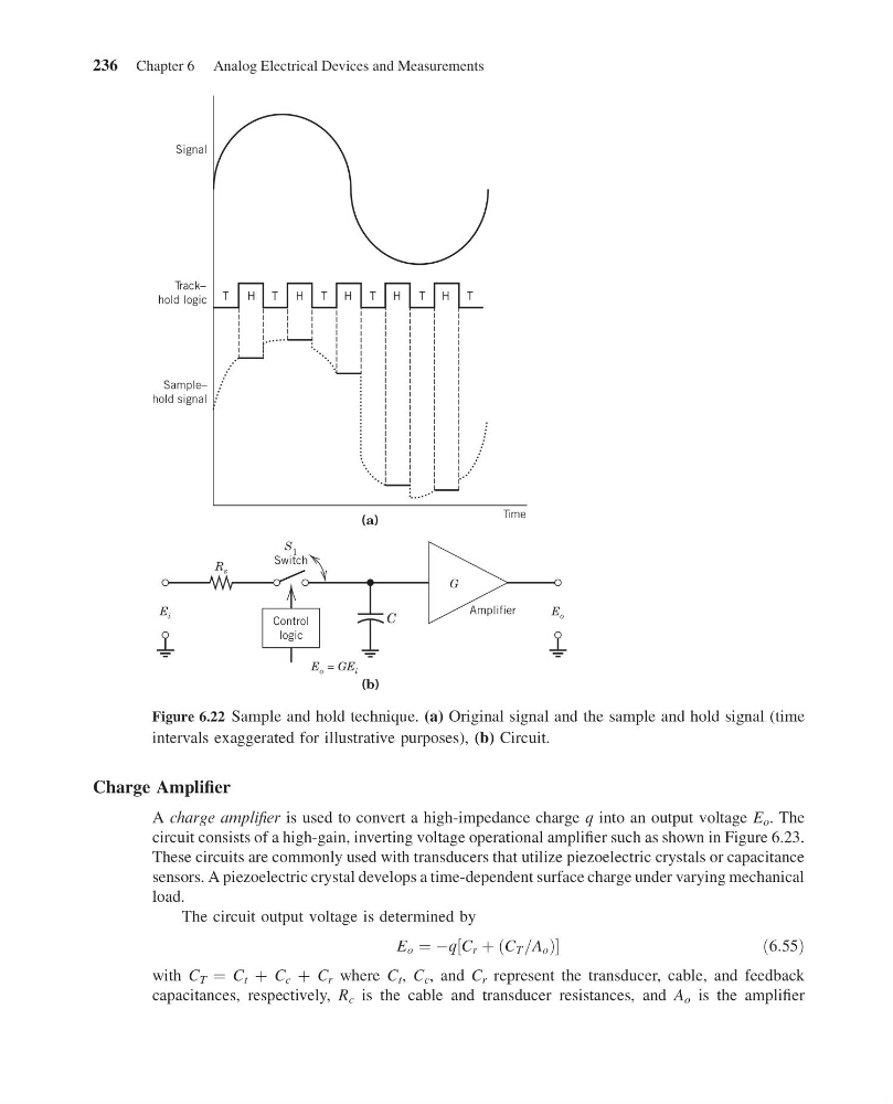
Figure 6.22 Sample and hold technique. (a) Original signal and the sample and hold signal (time
intervals exaggerated for illustrative purposes), (b) Circuit.
236 Chapter 6 Analog Electrical Devices and Measurements
11:55:6 Page 236
Charge Amplifier
A charge amplifier is used to convert a high-impedance charge q into an output voltage E o . The
circuit consists of a high-gain, inverting voltage operational amplifier such as shown in Figure 6.23.
These circuits are commonly used with transducers that utilize piezoelectric crystals or capacitance
sensors. A piezoelectric crystal develops a time-dependent surface charge under varying mechanical
load.
The circuit output voltage is determined by
E o ¼ Àq C r þ C T =A o
ð
Þ
½
ð 6:55Þ
with C T ¼ C t þ C c þ C r where C t , C c , and C r represent the transducer, cable, and feedback
capacitances, respectively, R c is the cable and transducer resistances, and A o is the amplifier
Signal
Track–
hold logic
Sample–
hold signal
H
H
T
T
T
T
T
T H
H
H
(a)
(b)
Time
E i
E o
G
E o = GE i
R s
Control
logic
S 1
Switch
C
Amplifier
Figure 6.22 Sample and hold technique. (a) Original signal and the sample and hold signal (time
intervals exaggerated for illustrative purposes), (b) Circuit.
236 Chapter 6 Analog Electrical Devices and Measurements