

E1C06 09/14/2010
11:55:4 Page 220
accurately measuring resistance, and for detecting very small changes in resistance. Figure 6.13
shows the basic arrangement for a bridge circuit, where R 1 is a sensor that experiences a change in
resistance associated with a change in some physical variable. A DC voltage is applied as an input
across nodes A to D, and the bridge forms a parallel circuit arrangement between these two nodes.
The currents flowing through the resistors R 1 to R 4 are I 1 to I 4 , respectively. Under the condition that
the current flow through the galvanometer, I g , is zero, the bridge is in a balanced condition
(alternatively, a current-sensing digital voltmeter might be used in place of the galvanometer).
A specific relationship exists between the resistances that form the bridge at balanced conditions.
To find this relationship, let I g ¼ 0. Under this balanced condition, there is no voltage drop from
B to C and
I 1 R 1 À I 3 R 3 ¼ 0
I 2 R 2 À I 4 R 4 ¼ 0
ð6:9Þ
Under balanced conditions, the current through the galvanometer is zero, and the currents through
the arms of the bridge are equal:
I 1 ¼ I 2 and I 3 ¼ I 4
ð6:10Þ
R 1
R 1
R 2
R 2
Circuit for a simple series ohmmeter
Zero adjust
DC voltage
supply
DC voltage
supply (battery)
Resistor
Zero
control
Range
select
Range select
D'Arsonval
meter movement
D'Arsonval
meter
movement
Unknown
resistance
Unknown
resistance
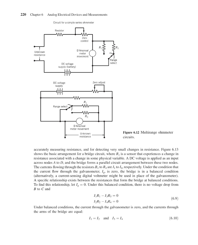
Figure 6.12 Multirange ohmmeter
circuits.
220 Chapter 6 Analog Electrical Devices and Measurements
11:55:4 Page 220
accurately measuring resistance, and for detecting very small changes in resistance. Figure 6.13
shows the basic arrangement for a bridge circuit, where R 1 is a sensor that experiences a change in
resistance associated with a change in some physical variable. A DC voltage is applied as an input
across nodes A to D, and the bridge forms a parallel circuit arrangement between these two nodes.
The currents flowing through the resistors R 1 to R 4 are I 1 to I 4 , respectively. Under the condition that
the current flow through the galvanometer, I g , is zero, the bridge is in a balanced condition
(alternatively, a current-sensing digital voltmeter might be used in place of the galvanometer).
A specific relationship exists between the resistances that form the bridge at balanced conditions.
To find this relationship, let I g ¼ 0. Under this balanced condition, there is no voltage drop from
B to C and
I 1 R 1 À I 3 R 3 ¼ 0
I 2 R 2 À I 4 R 4 ¼ 0
ð6:9Þ
Under balanced conditions, the current through the galvanometer is zero, and the currents through
the arms of the bridge are equal:
I 1 ¼ I 2 and I 3 ¼ I 4
ð6:10Þ
R 1
R 1
R 2
R 2
Circuit for a simple series ohmmeter
Zero adjust
DC voltage
supply
DC voltage
supply (battery)
Resistor
Zero
control
Range
select
Range select
D'Arsonval
meter movement
D'Arsonval
meter
movement
Unknown
resistance
Unknown
resistance
Figure 6.12 Multirange ohmmeter
circuits.
220 Chapter 6 Analog Electrical Devices and Measurements