

E1C06 09/14/2010
11:55:4 Page 219
6.4 ANALOG DEVICES: RESISTANCE MEASUREMENTS
Resistance measurements may range from simple continuity checks, to determining changes in
resistance on the order of 10
À6
V, to determining absolute resistance ranging from 10
À5 to 10
15
V.
As a result of the tremendous range of resistance values that have practical application, numerous
measurement techniques that are appropriate for specific ranges of resistance or resistance changes
have been developed. Some of these measurement systems and circuits provide necessary protection
for delicate instruments, allow compensation for changes in ambient conditions, or accommodate
changes in transducer reference points. In addition, the working principle of many transducers is
a change in resistance relative to a change in the measured variable. We will discuss the
measurement of resistance using basic techniques of voltage and current measurement in conjunction with Ohm’s law.
Ohmmeter Circuits
A simple way to measure resistance is by imposing a voltage across the unknown resistance and
measuring the resulting current flow where R ¼ E=I. Clearly, from Ohm’s law the value of resistance
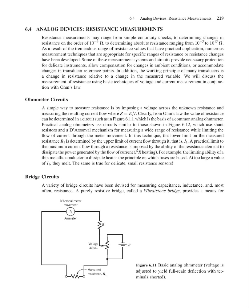
can be determined in a circuit such as in Figure 6.11, which is the basis of a common analog ohmmeter.
Practical analog ohmmeters use circuits similar to those shown in Figure 6.12, which use shunt
resistors and a D’Arsonval mechanism for measuring a wide range of resistance while limiting the
flow of current through the meter movement. In this technique, the lower limit on the measured
resistance R 1 is determined by the upper limit of current flow through it, that is, I 1 . A practical limit to
the maximum current flow through a resistance is imposed by the ability of the resistance element to
dissipate the power generated by the flow of current (I
2
R heating). For example, the limiting ability of a
thin metallic conductor to dissipate heat is the principle on which fuses are based. At too large a value
of I 1 , they melt. The same is true for delicate, small resistance sensors!
Bridge Circuits
A variety of bridge circuits have been devised for measuring capacitance, inductance, and, most
often, resistance. A purely resistive bridge, called a Wheatstone bridge, provides a means for
D’Arsonal meter
movement
Ammeter
I 1
R
Voltage
adjust
E
Measured
resistance, R 1
Figure 6.11 Basic analog ohmmeter (voltage is
adjusted to yield full-scale deflection with terminals shorted).
6.4 Analog Devices: Resistance Measurements 219
11:55:4 Page 219
6.4 ANALOG DEVICES: RESISTANCE MEASUREMENTS
Resistance measurements may range from simple continuity checks, to determining changes in
resistance on the order of 10
À6
V, to determining absolute resistance ranging from 10
À5 to 10
15
V.
As a result of the tremendous range of resistance values that have practical application, numerous
measurement techniques that are appropriate for specific ranges of resistance or resistance changes
have been developed. Some of these measurement systems and circuits provide necessary protection
for delicate instruments, allow compensation for changes in ambient conditions, or accommodate
changes in transducer reference points. In addition, the working principle of many transducers is
a change in resistance relative to a change in the measured variable. We will discuss the
measurement of resistance using basic techniques of voltage and current measurement in conjunction with Ohm’s law.
Ohmmeter Circuits
A simple way to measure resistance is by imposing a voltage across the unknown resistance and
measuring the resulting current flow where R ¼ E=I. Clearly, from Ohm’s law the value of resistance
can be determined in a circuit such as in Figure 6.11, which is the basis of a common analog ohmmeter.
Practical analog ohmmeters use circuits similar to those shown in Figure 6.12, which use shunt
resistors and a D’Arsonval mechanism for measuring a wide range of resistance while limiting the
flow of current through the meter movement. In this technique, the lower limit on the measured
resistance R 1 is determined by the upper limit of current flow through it, that is, I 1 . A practical limit to
the maximum current flow through a resistance is imposed by the ability of the resistance element to
dissipate the power generated by the flow of current (I
2
R heating). For example, the limiting ability of a
thin metallic conductor to dissipate heat is the principle on which fuses are based. At too large a value
of I 1 , they melt. The same is true for delicate, small resistance sensors!
Bridge Circuits
A variety of bridge circuits have been devised for measuring capacitance, inductance, and, most
often, resistance. A purely resistive bridge, called a Wheatstone bridge, provides a means for
D’Arsonal meter
movement
Ammeter
I 1
R
Voltage
adjust
E
Measured
resistance, R 1
Figure 6.11 Basic analog ohmmeter (voltage is
adjusted to yield full-scale deflection with terminals shorted).
6.4 Analog Devices: Resistance Measurements 219