

E1C06 09/14/2010
11:55:4 Page 218
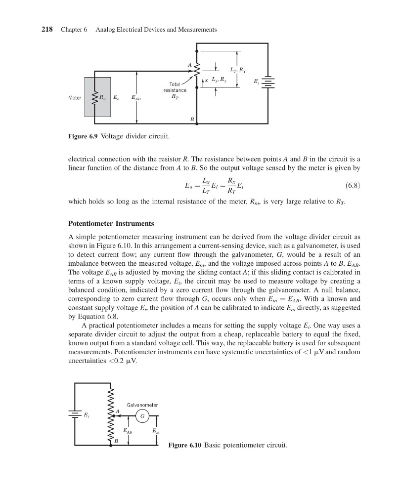
electrical connection with the resistor R. The resistance between points A and B in the circuit is a
linear function of the distance from A to B. So the output voltage sensed by the meter is given by
E o ¼
L x
L T
E i ¼
R x
R T
E i
ð6:8Þ
which holds so long as the internal resistance of the meter, R m , is very large relative to R T .
Potentiometer Instruments
A simple potentiometer measuring instrument can be derived from the voltage divider circuit as
shown in Figure 6.10. In this arrangement a current-sensing device, such as a galvanometer, is used
to detect current flow; any current flow through the galvanometer, G, would be a result of an
imbalance between the measured voltage, E m , and the voltage imposed across points A to B, E AB .
The voltage E AB is adjusted by moving the sliding contact A; if this sliding contact is calibrated in
terms of a known supply voltage, E i , the circuit may be used to measure voltage by creating a
balanced condition, indicated by a zero current flow through the galvanometer. A null balance,
corresponding to zero current flow through G, occurs only when E m ¼ E AB . With a known and
constant supply voltage E i , the position of A can be calibrated to indicate E m directly, as suggested
by Equation 6.8.
A practical potentiometer includes a means for setting the supply voltage E i . One way uses a
separate divider circuit to adjust the output from a cheap, replaceable battery to equal the fixed,
known output from a standard voltage cell. This way, the replaceable battery is used for subsequent
measurements. Potentiometer instruments can have systematic uncertainties of <1 mV and random
uncertainties <0.2 mV.
R m
E i
E AB
E o
L x , R x
L T , R T
B
A
x
Meter
Total
resistance
R T
Figure 6.9 Voltage divider circuit.
Galvanometer
A
B
E AB
E m
E i
G
Figure 6.10 Basic potentiometer circuit.
218 Chapter 6 Analog Electrical Devices and Measurements
11:55:4 Page 218
electrical connection with the resistor R. The resistance between points A and B in the circuit is a
linear function of the distance from A to B. So the output voltage sensed by the meter is given by
E o ¼
L x
L T
E i ¼
R x
R T
E i
ð6:8Þ
which holds so long as the internal resistance of the meter, R m , is very large relative to R T .
Potentiometer Instruments
A simple potentiometer measuring instrument can be derived from the voltage divider circuit as
shown in Figure 6.10. In this arrangement a current-sensing device, such as a galvanometer, is used
to detect current flow; any current flow through the galvanometer, G, would be a result of an
imbalance between the measured voltage, E m , and the voltage imposed across points A to B, E AB .
The voltage E AB is adjusted by moving the sliding contact A; if this sliding contact is calibrated in
terms of a known supply voltage, E i , the circuit may be used to measure voltage by creating a
balanced condition, indicated by a zero current flow through the galvanometer. A null balance,
corresponding to zero current flow through G, occurs only when E m ¼ E AB . With a known and
constant supply voltage E i , the position of A can be calibrated to indicate E m directly, as suggested
by Equation 6.8.
A practical potentiometer includes a means for setting the supply voltage E i . One way uses a
separate divider circuit to adjust the output from a cheap, replaceable battery to equal the fixed,
known output from a standard voltage cell. This way, the replaceable battery is used for subsequent
measurements. Potentiometer instruments can have systematic uncertainties of <1 mV and random
uncertainties <0.2 mV.
R m
E i
E AB
E o
L x , R x
L T , R T
B
A
x
Meter
Total
resistance
R T
Figure 6.9 Voltage divider circuit.
Galvanometer
A
B
E AB
E m
E i
G
Figure 6.10 Basic potentiometer circuit.
218 Chapter 6 Analog Electrical Devices and Measurements