

E1C06 09/14/2010
11:55:4 Page 221
Solving Equations 6.9 simultaneously, with the condition stated in Equation 6.10, yields the
necessary relationship among the resistances for a balanced bridge:
R 2
R 1
¼
R 4
R 3
ð6:11Þ
Resistance and resistance change can be measured in one of two ways with this bridge circuit. If
the resistor R 1 varies with changes in the measured physical variable, one of the other arms of the
bridge can be adjusted to null the circuit and determine resistance. Another method uses a voltage
measuring device to measure the voltage unbalance in the bridge as an indication of the change in
resistance. Both of these methods will be analyzed further.
Null Method
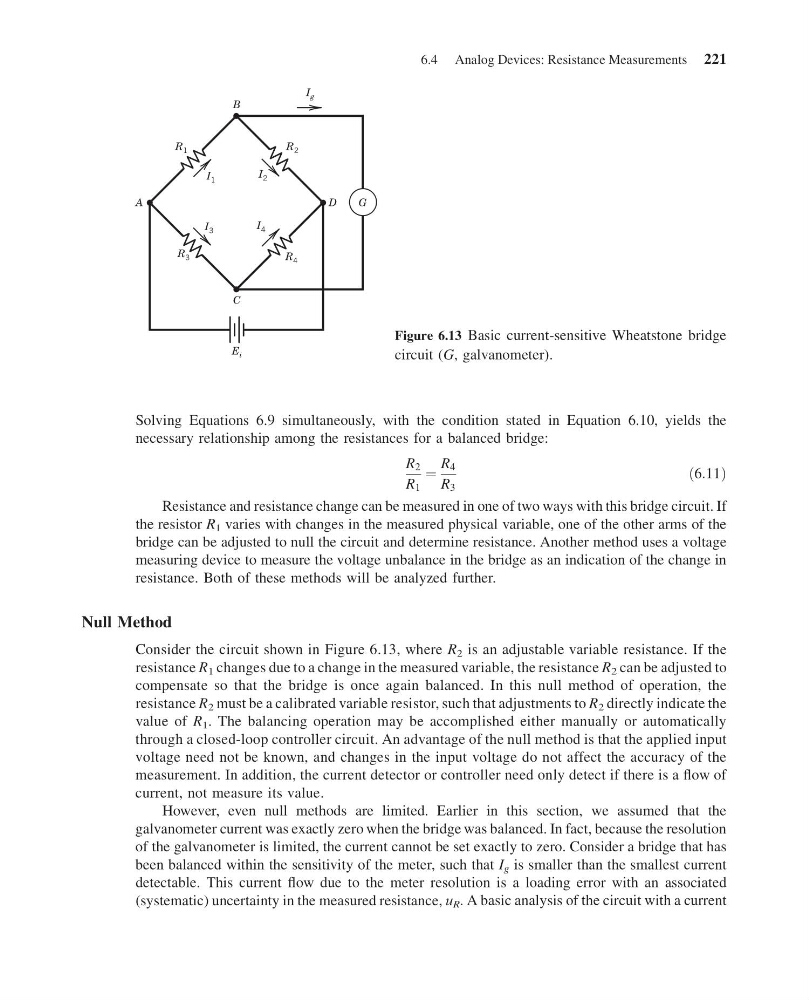
Consider the circuit shown in Figure 6.13, where R 2 is an adjustable variable resistance. If the
resistance R 1 changes due to a change in the measured variable, the resistance R 2 can be adjusted to
compensate so that the bridge is once again balanced. In this null method of operation, the
resistance R 2 must be a calibrated variable resistor, such that adjustments to R 2 directly indicate the
value of R 1 . The balancing operation may be accomplished either manually or automatically
through a closed-loop controller circuit. An advantage of the null method is that the applied input
voltage need not be known, and changes in the input voltage do not affect the accuracy of the
measurement. In addition, the current detector or controller need only detect if there is a flow of
current, not measure its value.
However, even null methods are limited. Earlier in this section, we assumed that the
galvanometer current was exactly zero when the bridge was balanced. In fact, because the resolution
of the galvanometer is limited, the current cannot be set exactly to zero. Consider a bridge that has
been balanced within the sensitivity of the meter, such that I g is smaller than the smallest current
detectable. This current flow due to the meter resolution is a loading error with an associated
(systematic) uncertainty in the measured resistance, u R . A basic analysis of the circuit with a current
I g
B
C
A
D
R 4
R 1
R 3
R 2
I 2
I 3
I 1
I 4
E i
G
Figure 6.13 Basic current-sensitive Wheatstone bridge
circuit (G, galvanometer).
6.4 Analog Devices: Resistance Measurements 221
11:55:4 Page 221
Solving Equations 6.9 simultaneously, with the condition stated in Equation 6.10, yields the
necessary relationship among the resistances for a balanced bridge:
R 2
R 1
¼
R 4
R 3
ð6:11Þ
Resistance and resistance change can be measured in one of two ways with this bridge circuit. If
the resistor R 1 varies with changes in the measured physical variable, one of the other arms of the
bridge can be adjusted to null the circuit and determine resistance. Another method uses a voltage
measuring device to measure the voltage unbalance in the bridge as an indication of the change in
resistance. Both of these methods will be analyzed further.
Null Method
Consider the circuit shown in Figure 6.13, where R 2 is an adjustable variable resistance. If the
resistance R 1 changes due to a change in the measured variable, the resistance R 2 can be adjusted to
compensate so that the bridge is once again balanced. In this null method of operation, the
resistance R 2 must be a calibrated variable resistor, such that adjustments to R 2 directly indicate the
value of R 1 . The balancing operation may be accomplished either manually or automatically
through a closed-loop controller circuit. An advantage of the null method is that the applied input
voltage need not be known, and changes in the input voltage do not affect the accuracy of the
measurement. In addition, the current detector or controller need only detect if there is a flow of
current, not measure its value.
However, even null methods are limited. Earlier in this section, we assumed that the
galvanometer current was exactly zero when the bridge was balanced. In fact, because the resolution
of the galvanometer is limited, the current cannot be set exactly to zero. Consider a bridge that has
been balanced within the sensitivity of the meter, such that I g is smaller than the smallest current
detectable. This current flow due to the meter resolution is a loading error with an associated
(systematic) uncertainty in the measured resistance, u R . A basic analysis of the circuit with a current
I g
B
C
A
D
R 4
R 1
R 3
R 2
I 2
I 3
I 1
I 4
E i
G
Figure 6.13 Basic current-sensitive Wheatstone bridge
circuit (G, galvanometer).
6.4 Analog Devices: Resistance Measurements 221