

E1C06 09/14/2010
11:55:3 Page 214
Equations 6.5 and 6.6 define the coupling relations between the mechanical Equation 6.4 and the
electrical Equation 6.7. From these, we see that the current due to potential E brings about developed
torque T m that moves the galvanometer pointer, and that this motion is opposed by the mechanical
restoring force of the spring and by the development of an opposing electrical potential E m . The
system damping allows the pointer to settle to an equilibrium position.
COMMENT The system output, which is the pointer movement here, is governed by the
second-order system response described in Chapter 3. However, the torque input to the mechanical
system is a function of the electrical response of the system. In this measurement system, the input
signal, which is the applied voltage here, is transformed into a mechanical torque to provide the
measurable output deflection.
6.3 ANALOG DEVICES: VOLTAGE MEASUREMENTS
Often we are interested in measuring either static or dynamic voltage signals. Depending on the
source, the magnitude of these signals may range over several orders of magnitude throughout the
measured signal chain. The frequency content of dynamic voltage signals is often of interest as well.
As such, a wide variety of measurement systems have been developed for voltage measurement of
static and dynamic signals. This section discusses several convenient and common methods to
indicate voltage in measurement systems.
Analog Voltage Meters
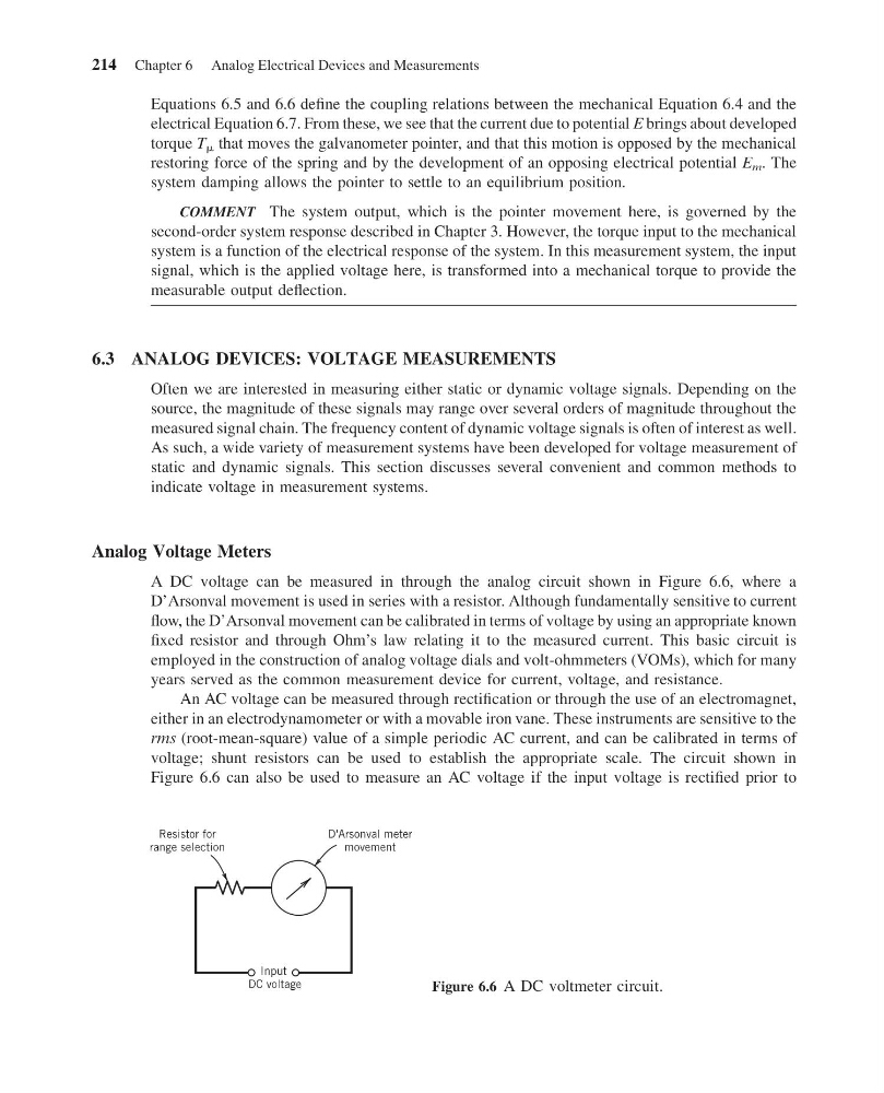
A DC voltage can be measured in through the analog circuit shown in Figure 6.6, where a
D’Arsonval movement is used in series with a resistor. Although fundamentally sensitive to current
flow, the D’Arsonval movement can be calibrated in terms of voltage by using an appropriate known
fixed resistor and through Ohm’s law relating it to the measured current. This basic circuit is
employed in the construction of analog voltage dials and volt-ohmmeters (VOMs), which for many
years served as the common measurement device for current, voltage, and resistance.
An AC voltage can be measured through rectification or through the use of an electromagnet,
either in an electrodynamometer or with a movable iron vane. These instruments are sensitive to the
rms (root-mean-square) value of a simple periodic AC current, and can be calibrated in terms of
voltage; shunt resistors can be used to establish the appropriate scale. The circuit shown in
Figure 6.6 can also be used to measure an AC voltage if the input voltage is rectified prior to
Resistor for
range selection
D'Arsonval meter
movement
Input
DC voltage
Figure 6.6 A DC voltmeter circuit.
214 Chapter 6 Analog Electrical Devices and Measurements
11:55:3 Page 214
Equations 6.5 and 6.6 define the coupling relations between the mechanical Equation 6.4 and the
electrical Equation 6.7. From these, we see that the current due to potential E brings about developed
torque T m that moves the galvanometer pointer, and that this motion is opposed by the mechanical
restoring force of the spring and by the development of an opposing electrical potential E m . The
system damping allows the pointer to settle to an equilibrium position.
COMMENT The system output, which is the pointer movement here, is governed by the
second-order system response described in Chapter 3. However, the torque input to the mechanical
system is a function of the electrical response of the system. In this measurement system, the input
signal, which is the applied voltage here, is transformed into a mechanical torque to provide the
measurable output deflection.
6.3 ANALOG DEVICES: VOLTAGE MEASUREMENTS
Often we are interested in measuring either static or dynamic voltage signals. Depending on the
source, the magnitude of these signals may range over several orders of magnitude throughout the
measured signal chain. The frequency content of dynamic voltage signals is often of interest as well.
As such, a wide variety of measurement systems have been developed for voltage measurement of
static and dynamic signals. This section discusses several convenient and common methods to
indicate voltage in measurement systems.
Analog Voltage Meters
A DC voltage can be measured in through the analog circuit shown in Figure 6.6, where a
D’Arsonval movement is used in series with a resistor. Although fundamentally sensitive to current
flow, the D’Arsonval movement can be calibrated in terms of voltage by using an appropriate known
fixed resistor and through Ohm’s law relating it to the measured current. This basic circuit is
employed in the construction of analog voltage dials and volt-ohmmeters (VOMs), which for many
years served as the common measurement device for current, voltage, and resistance.
An AC voltage can be measured through rectification or through the use of an electromagnet,
either in an electrodynamometer or with a movable iron vane. These instruments are sensitive to the
rms (root-mean-square) value of a simple periodic AC current, and can be calibrated in terms of
voltage; shunt resistors can be used to establish the appropriate scale. The circuit shown in
Figure 6.6 can also be used to measure an AC voltage if the input voltage is rectified prior to
Resistor for
range selection
D'Arsonval meter
movement
Input
DC voltage
Figure 6.6 A DC voltmeter circuit.
214 Chapter 6 Analog Electrical Devices and Measurements