

E1C06 09/14/2010
11:55:3 Page 215
input to this circuit. The waveform output of the rectifier must be considered if a steady meter
reading is to be obtained. An AC meter indicates a true rms value for a simple periodic signal only,
but a true rms AC voltmeter performs the signal integration (e.g., Eq. 2.4) required to accurately
determine the rms value in a signal-conditioning stage and indicates true signal rms regardless
of waveform.
Oscilloscope
The oscilloscope is a practical graphical display device providing an analog representation of a
measured signal. It is used to measure and to visually display voltage magnitude versus time for
dynamic signals over a wide range of frequencies with a signal bandwidth extending commonly into
the megahertz range and, with some units, into the gigahertz range (1, 2). A useful diagnostic tool, the
oscilloscope provides a visual output of signal magnitude, frequency, distortion, and a delineation of
the DC and AC components. The visual image provides a direct means to detect the superposition of
noise and interference on a measured signal, something nonvisual metering devices cannot do. In
addition to signal versus time, a typical unit can also display two or more signals [X(t) and Y(t)],
perform addition and subtraction of signals (X þ Y, X À Y), and display amplitude versus amplitude
(XY) plots and other features. Some digital oscilloscopes have significant internal storage so as to
mimic a data-logging signal recorder. Others have internal fast Fourier transform (FFT) circuitry to
provide for direct spectral analysis of a signal (see Chapter 2).
Although seen less often today, the cathode ray oscilloscope is interesting in that the cathode
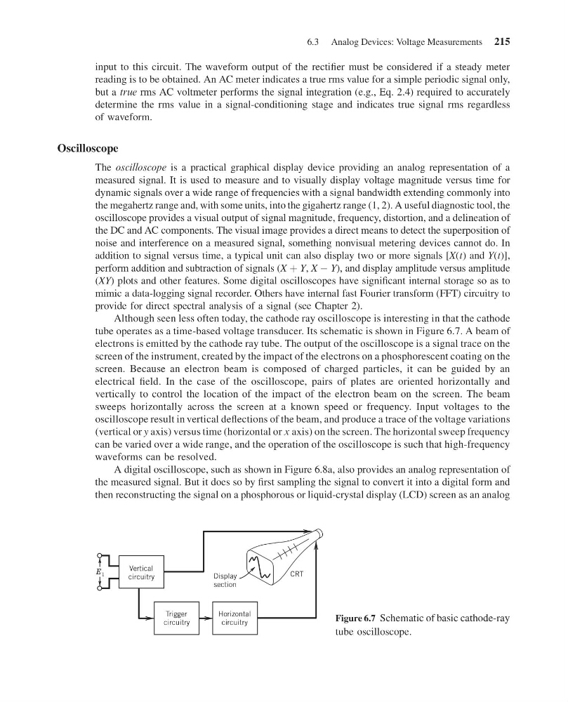
tube operates as a time-based voltage transducer. Its schematic is shown in Figure 6.7. A beam of
electrons is emitted by the cathode ray tube. The output of the oscilloscope is a signal trace on the
screen of the instrument, created by the impact of the electrons on a phosphorescent coating on the
screen. Because an electron beam is composed of charged particles, it can be guided by an
electrical field. In the case of the oscilloscope, pairs of plates are oriented horizontally and
vertically to control the location of the impact of the electron beam on the screen. The beam
sweeps horizontally across the screen at a known speed or frequency. Input voltages to the
oscilloscope result in vertical deflections of the beam, and produce a trace of the voltage variations
(vertical or y axis) versus time (horizontal or x axis) on the screen. The horizontal sweep frequency
can be varied over a wide range, and the operation of the oscilloscope is such that high-frequency
waveforms can be resolved.
A digital oscilloscope, such as shown in Figure 6.8a, also provides an analog representation of
the measured signal. But it does so by first sampling the signal to convert it into a digital form and
then reconstructing the signal on a phosphorous or liquid-crystal display (LCD) screen as an analog
Display
section
Vertical
circuitry
Trigger
circuitry
Horizontal
circuitry
CRT
E 1
Figure 6.7 Schematic of basic cathode-ray
tube oscilloscope.
6.3 Analog Devices: Voltage Measurements 215
11:55:3 Page 215
input to this circuit. The waveform output of the rectifier must be considered if a steady meter
reading is to be obtained. An AC meter indicates a true rms value for a simple periodic signal only,
but a true rms AC voltmeter performs the signal integration (e.g., Eq. 2.4) required to accurately
determine the rms value in a signal-conditioning stage and indicates true signal rms regardless
of waveform.
Oscilloscope
The oscilloscope is a practical graphical display device providing an analog representation of a
measured signal. It is used to measure and to visually display voltage magnitude versus time for
dynamic signals over a wide range of frequencies with a signal bandwidth extending commonly into
the megahertz range and, with some units, into the gigahertz range (1, 2). A useful diagnostic tool, the
oscilloscope provides a visual output of signal magnitude, frequency, distortion, and a delineation of
the DC and AC components. The visual image provides a direct means to detect the superposition of
noise and interference on a measured signal, something nonvisual metering devices cannot do. In
addition to signal versus time, a typical unit can also display two or more signals [X(t) and Y(t)],
perform addition and subtraction of signals (X þ Y, X À Y), and display amplitude versus amplitude
(XY) plots and other features. Some digital oscilloscopes have significant internal storage so as to
mimic a data-logging signal recorder. Others have internal fast Fourier transform (FFT) circuitry to
provide for direct spectral analysis of a signal (see Chapter 2).
Although seen less often today, the cathode ray oscilloscope is interesting in that the cathode
tube operates as a time-based voltage transducer. Its schematic is shown in Figure 6.7. A beam of
electrons is emitted by the cathode ray tube. The output of the oscilloscope is a signal trace on the
screen of the instrument, created by the impact of the electrons on a phosphorescent coating on the
screen. Because an electron beam is composed of charged particles, it can be guided by an
electrical field. In the case of the oscilloscope, pairs of plates are oriented horizontally and
vertically to control the location of the impact of the electron beam on the screen. The beam
sweeps horizontally across the screen at a known speed or frequency. Input voltages to the
oscilloscope result in vertical deflections of the beam, and produce a trace of the voltage variations
(vertical or y axis) versus time (horizontal or x axis) on the screen. The horizontal sweep frequency
can be varied over a wide range, and the operation of the oscilloscope is such that high-frequency
waveforms can be resolved.
A digital oscilloscope, such as shown in Figure 6.8a, also provides an analog representation of
the measured signal. But it does so by first sampling the signal to convert it into a digital form and
then reconstructing the signal on a phosphorous or liquid-crystal display (LCD) screen as an analog
Display
section
Vertical
circuitry
Trigger
circuitry
Horizontal
circuitry
CRT
E 1
Figure 6.7 Schematic of basic cathode-ray
tube oscilloscope.
6.3 Analog Devices: Voltage Measurements 215