

E1C06 09/14/2010
11:55:2 Page 213
unknown current and used to concentrate the magnetic field, and a Hall-effect sensor that is attached to
the iron core so as to be aligned parallel to the wire of an unknown current being measured.
Example 6.1
A galvanometer consists of N turns of a conductor wound about a core of length l and radius r that is
situated perpendicular to a magnetic field of uniform flux density B. A DC current passes through the
conductor due to an applied potential, E i (t). The output of the device is the rotation of the core and
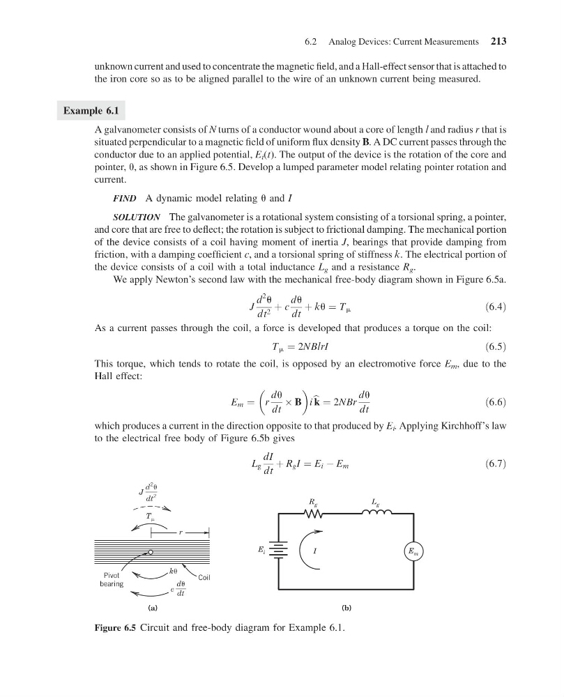
pointer, u, as shown in Figure 6.5. Develop a lumped parameter model relating pointer rotation and
current.
FIND A dynamic model relating u and I
SOLUTION The galvanometer is a rotational system consisting of a torsional spring, a pointer,
and core that are free to deflect; the rotation is subject to frictional damping. The mechanical portion
of the device consists of a coil having moment of inertia J, bearings that provide damping from
friction, with a damping coefficient c, and a torsional spring of stiffness k. The electrical portion of
the device consists of a coil with a total inductance L g and a resistance R g .
We apply Newton’s second law with the mechanical free-body diagram shown in Figure 6.5a.
J
d
2
u
dt 2 þ c
du
dt
þ ku ¼ T m
ð6:4Þ
As a current passes through the coil, a force is developed that produces a torque on the coil:
T m ¼ 2NBlrI
ð6:5Þ
This torque, which tends to rotate the coil, is opposed by an electromotive force E m , due to the
Hall effect:
E m ¼ r
du
dt
 B
i b k ¼ 2NBr
du
dt
ð6:6Þ
which produces a current in the direction opposite to that produced by E i . Applying Kirchhoff’s law
to the electrical free body of Figure 6.5b gives
L g
dI
dt
þ R g I ¼ E i À E m
ð6:7Þ
d
2
dt
2
J
d
dt
c
T
r
(a)
( b)
k
E i
E m
R g
L g
I
Pivot
bearing
Coil
Figure 6.5 Circuit and free-body diagram for Example 6.1.
6.2 Analog Devices: Current Measurements 213
11:55:2 Page 213
unknown current and used to concentrate the magnetic field, and a Hall-effect sensor that is attached to
the iron core so as to be aligned parallel to the wire of an unknown current being measured.
Example 6.1
A galvanometer consists of N turns of a conductor wound about a core of length l and radius r that is
situated perpendicular to a magnetic field of uniform flux density B. A DC current passes through the
conductor due to an applied potential, E i (t). The output of the device is the rotation of the core and
pointer, u, as shown in Figure 6.5. Develop a lumped parameter model relating pointer rotation and
current.
FIND A dynamic model relating u and I
SOLUTION The galvanometer is a rotational system consisting of a torsional spring, a pointer,
and core that are free to deflect; the rotation is subject to frictional damping. The mechanical portion
of the device consists of a coil having moment of inertia J, bearings that provide damping from
friction, with a damping coefficient c, and a torsional spring of stiffness k. The electrical portion of
the device consists of a coil with a total inductance L g and a resistance R g .
We apply Newton’s second law with the mechanical free-body diagram shown in Figure 6.5a.
J
d
2
u
dt 2 þ c
du
dt
þ ku ¼ T m
ð6:4Þ
As a current passes through the coil, a force is developed that produces a torque on the coil:
T m ¼ 2NBlrI
ð6:5Þ
This torque, which tends to rotate the coil, is opposed by an electromotive force E m , due to the
Hall effect:
E m ¼ r
du
dt
 B
i b k ¼ 2NBr
du
dt
ð6:6Þ
which produces a current in the direction opposite to that produced by E i . Applying Kirchhoff’s law
to the electrical free body of Figure 6.5b gives
L g
dI
dt
þ R g I ¼ E i À E m
ð6:7Þ
d
2
dt
2
J
d
dt
c
T
r
(a)
( b)
k
E i
E m
R g
L g
I
Pivot
bearing
Coil
Figure 6.5 Circuit and free-body diagram for Example 6.1.
6.2 Analog Devices: Current Measurements 213