

E1C06 09/14/2010
11:55:2 Page 212
Errors inherent to the D’Arsonval movement include hysteresis and repeatability errors due to
mechanical friction in the pointer-bearing movement, and linearity errors in the spring that provides
the restoring force for equilibrium. Also, in developing a torque, the D’Arsonval movement must
extract energy from the current flowing through it. This draining of energy from the signal being
measured changes the measured signal, and such an effect is called a loading error. This is a
consequence of all instruments that operate in deflection mode. A quantitative analysis of loading
errors is provided later.
Alternating Current
An AC current can be measured in any number of ways. One technique, found in common deflection
meters, uses diodes to form a rectifier that converts the time-dependent AC current into a DC current.
This current then can be measured with a calibrated D’Arsonval movement meter as previously
described. This is the same technique used in those ubiquitous small transformers used to convert
AC wall current into a DC current at a set voltage to power or to charge electronic devices. An
electrodynamometer is basically a D’Arsonval movement modified for use with AC current by
replacing the permanent magnet with an electromagnet in series with the current coil. These AC
meters have upper limits on the frequency of the alternating current that they can effectively
measure; most common instruments are calibrated for use with standard line frequency.
An accurate measuring solution for large AC current is the Hall effect probe. This is a probe
clamped over the current-carrying wire (conductor) to measure its unknown current flow. To
understand its use, let us mention two phenomena. The first is the Hall effect, which is a voltage that
is developed from any current-carrying conductor placed perpendicular to a magnetic field. For a
known current, the magnitude of this voltage directly depends on the magnitude of the magnetic
field. The second is that a current passing through a wire generates a magnetic field. So in practice, a
Hall-effect probe is realized by coupling these two processes concurrently: use the unknown current
within a wire to generate a magnetic field that develops a measurable voltage across a Hall-effect
sensor.
The Hall-effect sensor is a thin conducting semiconductor wafer driven by a known current; this
current is unrelated to the unknown current being measured and is provided by a separate source,
such as a battery. The Hall-effect probe is an iron-core ring that is placed around the wire of an
R 3
R 2
R 1
Range
switch
Current
input
Shunt resistors
D'Arsonval
meter movement
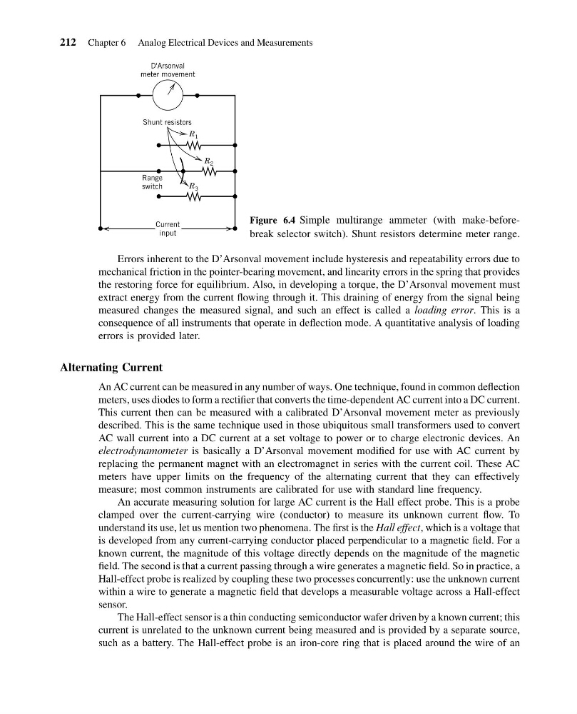
Figure 6.4 Simple multirange ammeter (with make-beforebreak selector switch). Shunt resistors determine meter range.
212 Chapter 6 Analog Electrical Devices and Measurements
11:55:2 Page 212
Errors inherent to the D’Arsonval movement include hysteresis and repeatability errors due to
mechanical friction in the pointer-bearing movement, and linearity errors in the spring that provides
the restoring force for equilibrium. Also, in developing a torque, the D’Arsonval movement must
extract energy from the current flowing through it. This draining of energy from the signal being
measured changes the measured signal, and such an effect is called a loading error. This is a
consequence of all instruments that operate in deflection mode. A quantitative analysis of loading
errors is provided later.
Alternating Current
An AC current can be measured in any number of ways. One technique, found in common deflection
meters, uses diodes to form a rectifier that converts the time-dependent AC current into a DC current.
This current then can be measured with a calibrated D’Arsonval movement meter as previously
described. This is the same technique used in those ubiquitous small transformers used to convert
AC wall current into a DC current at a set voltage to power or to charge electronic devices. An
electrodynamometer is basically a D’Arsonval movement modified for use with AC current by
replacing the permanent magnet with an electromagnet in series with the current coil. These AC
meters have upper limits on the frequency of the alternating current that they can effectively
measure; most common instruments are calibrated for use with standard line frequency.
An accurate measuring solution for large AC current is the Hall effect probe. This is a probe
clamped over the current-carrying wire (conductor) to measure its unknown current flow. To
understand its use, let us mention two phenomena. The first is the Hall effect, which is a voltage that
is developed from any current-carrying conductor placed perpendicular to a magnetic field. For a
known current, the magnitude of this voltage directly depends on the magnitude of the magnetic
field. The second is that a current passing through a wire generates a magnetic field. So in practice, a
Hall-effect probe is realized by coupling these two processes concurrently: use the unknown current
within a wire to generate a magnetic field that develops a measurable voltage across a Hall-effect
sensor.
The Hall-effect sensor is a thin conducting semiconductor wafer driven by a known current; this
current is unrelated to the unknown current being measured and is provided by a separate source,
such as a battery. The Hall-effect probe is an iron-core ring that is placed around the wire of an
R 3
R 2
R 1
Range
switch
Current
input
Shunt resistors
D'Arsonval
meter movement
Figure 6.4 Simple multirange ammeter (with make-beforebreak selector switch). Shunt resistors determine meter range.
212 Chapter 6 Analog Electrical Devices and Measurements