

10.8 Racetrack Memory
259
Table 10.3 Comparison
between skyrmions and
domain walls
Skyrmion
Domain wall
Size (nm)
10–50
20–50
Speed (m/s)
~100
~500–750
Critical current (A/Cm 2 )
10 2
10 7
memory state from 1 to 0) of all the spins in the conventional domains needs substantial power where as skyrmions need fewer spin flips to switch. Another advantage
is that the final spin state is not easily disrupted either, which makes these skyrmion
structures steadier than their usual counterpart.
Magnetic skyrmions can be driven by a spin transfer torque mechanism at a
very low current density. This is a technologically exciting property and has made
skyrmion a promising candidate for racetrack memory. The skyrmion motion has
been demonstrated in a multilayer of Ta/CoFeB/Ta-O at the speed of ~10 m/s at
room temperature. Further increase in the speed >100 m/s can then be achieved
in Pt/CoFeB/MgO. Using such current-induced skyrmion motion, skyrmion logic
has been proposed and demonstrated. Using a ‘Y’-shaped wire, both AND and OR
operations have been verified. The size of the skyrmions can also be controlled by
applied magnetic field. Both the methods (i.e., DW and Skyrmion) have their own
advantages and disadvantages. A comparative chart is presented in Table 10.3.
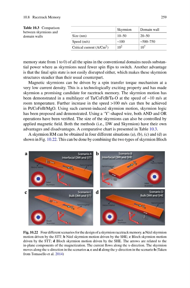
A skyrmion RM can be obtained in four different situations (a), (b), (c) and (d) as
shown in Fig. 10.22. This can be done by combining the two types of skyrmion Bloch
Fig. 10.22 Four different scenarios for the design of a skyrmion racetrack memory. a Néel skyrmion
motion driven by the STT; b Néel skyrmion motion driven by the SHE; c Bloch skyrmion motion
driven by the STT; d Bloch skyrmion motion driven by the SHE. The arrows are related to the
in-plane components of the magnetization. The current flows along the x-direction. The skyrmion
moves along the x-direction in the scenarios a, c and d along the y-direction in the scenario b (Taken
from Tomasello et al. 2014)
259
Table 10.3 Comparison
between skyrmions and
domain walls
Skyrmion
Domain wall
Size (nm)
10–50
20–50
Speed (m/s)
~100
~500–750
Critical current (A/Cm 2 )
10 2
10 7
memory state from 1 to 0) of all the spins in the conventional domains needs substantial power where as skyrmions need fewer spin flips to switch. Another advantage
is that the final spin state is not easily disrupted either, which makes these skyrmion
structures steadier than their usual counterpart.
Magnetic skyrmions can be driven by a spin transfer torque mechanism at a
very low current density. This is a technologically exciting property and has made
skyrmion a promising candidate for racetrack memory. The skyrmion motion has
been demonstrated in a multilayer of Ta/CoFeB/Ta-O at the speed of ~10 m/s at
room temperature. Further increase in the speed >100 m/s can then be achieved
in Pt/CoFeB/MgO. Using such current-induced skyrmion motion, skyrmion logic
has been proposed and demonstrated. Using a ‘Y’-shaped wire, both AND and OR
operations have been verified. The size of the skyrmions can also be controlled by
applied magnetic field. Both the methods (i.e., DW and Skyrmion) have their own
advantages and disadvantages. A comparative chart is presented in Table 10.3.
A skyrmion RM can be obtained in four different situations (a), (b), (c) and (d) as
shown in Fig. 10.22. This can be done by combining the two types of skyrmion Bloch
Fig. 10.22 Four different scenarios for the design of a skyrmion racetrack memory. a Néel skyrmion
motion driven by the STT; b Néel skyrmion motion driven by the SHE; c Bloch skyrmion motion
driven by the STT; d Bloch skyrmion motion driven by the SHE. The arrows are related to the
in-plane components of the magnetization. The current flows along the x-direction. The skyrmion
moves along the x-direction in the scenarios a, c and d along the y-direction in the scenario b (Taken
from Tomasello et al. 2014)