

246
10 Spintronics Applications
10.6.2 Some GMR-Based Sensors Applications
After the introduction of the first commercial GMR sensors in 1995, there has been a
rapid evolution of GMR sensors technology. Eventually, this has explored a wide
and promising range of applications. Nowadays, GMR-based sensors are being
applied in diverse fields, such as engineering, physics, biology, space, etc. Following
discussions are focussed on the direct and indirect GMR-based applications.
Electrical Current Sensing
In conventional approach, electrical current is measured by using shunt resistances,
coils and solid-state sensors. On the other hand, solid-state magnetic sensor can sense
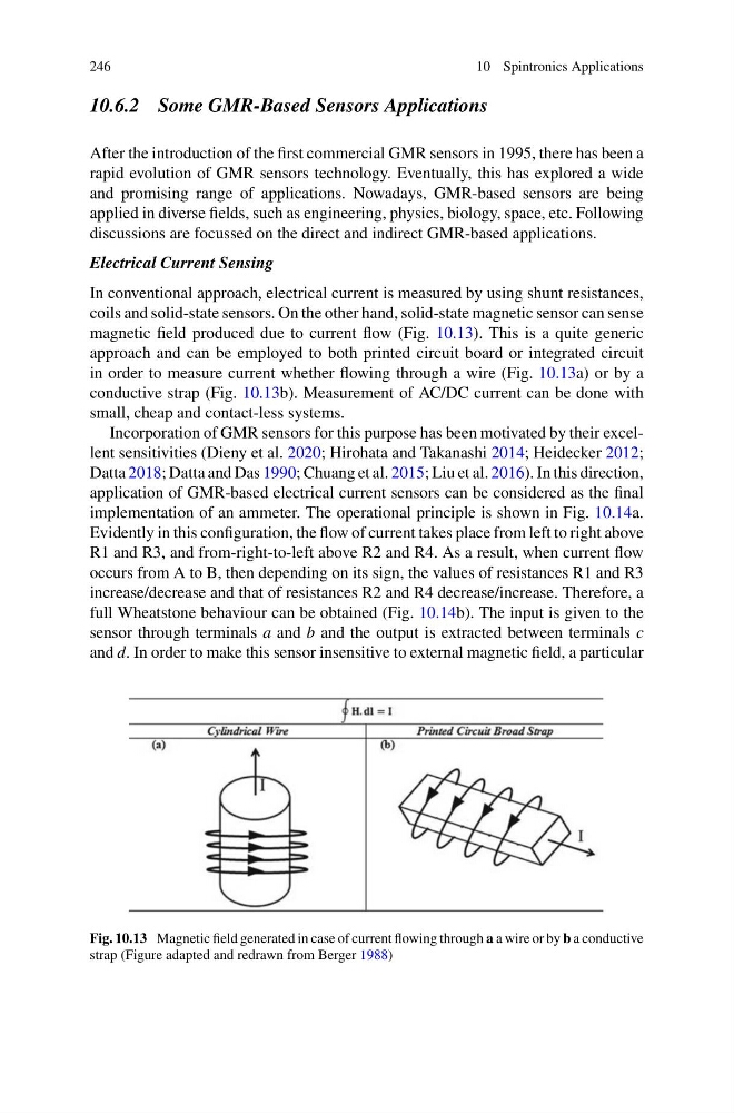
magnetic field produced due to current flow (Fig. 10.13). This is a quite generic
approach and can be employed to both printed circuit board or integrated circuit
in order to measure current whether flowing through a wire (Fig. 10.13a) or by a
conductive strap (Fig. 10.13b). Measurement of AC/DC current can be done with
small, cheap and contact-less systems.
Incorporation of GMR sensors for this purpose has been motivated by their excellent sensitivities (Dieny et al. 2020; Hirohata and Takanashi 2014; Heidecker 2012;
Datta 2018; Datta and Das 1990; Chuang et al. 2015; Liu et al. 2016). In this direction,
application of GMR-based electrical current sensors can be considered as the final
implementation of an ammeter. The operational principle is shown in Fig. 10.14a.
Evidently in this configuration, the flow of current takes place from left to right above
R1 and R3, and from-right-to-left above R2 and R4. As a result, when current flow
occurs from A to B, then depending on its sign, the values of resistances R1 and R3
increase/decrease and that of resistances R2 and R4 decrease/increase. Therefore, a
full Wheatstone behaviour can be obtained (Fig. 10.14b). The input is given to the
sensor through terminals a and b and the output is extracted between terminals c
and d. In order to make this sensor insensitive to external magnetic field, a particular
Fig. 10.13 Magnetic field generated in case of current flowing through a a wire or by b a conductive
strap (Figure adapted and redrawn from Berger 1988)
10 Spintronics Applications
10.6.2 Some GMR-Based Sensors Applications
After the introduction of the first commercial GMR sensors in 1995, there has been a
rapid evolution of GMR sensors technology. Eventually, this has explored a wide
and promising range of applications. Nowadays, GMR-based sensors are being
applied in diverse fields, such as engineering, physics, biology, space, etc. Following
discussions are focussed on the direct and indirect GMR-based applications.
Electrical Current Sensing
In conventional approach, electrical current is measured by using shunt resistances,
coils and solid-state sensors. On the other hand, solid-state magnetic sensor can sense
magnetic field produced due to current flow (Fig. 10.13). This is a quite generic
approach and can be employed to both printed circuit board or integrated circuit
in order to measure current whether flowing through a wire (Fig. 10.13a) or by a
conductive strap (Fig. 10.13b). Measurement of AC/DC current can be done with
small, cheap and contact-less systems.
Incorporation of GMR sensors for this purpose has been motivated by their excellent sensitivities (Dieny et al. 2020; Hirohata and Takanashi 2014; Heidecker 2012;
Datta 2018; Datta and Das 1990; Chuang et al. 2015; Liu et al. 2016). In this direction,
application of GMR-based electrical current sensors can be considered as the final
implementation of an ammeter. The operational principle is shown in Fig. 10.14a.
Evidently in this configuration, the flow of current takes place from left to right above
R1 and R3, and from-right-to-left above R2 and R4. As a result, when current flow
occurs from A to B, then depending on its sign, the values of resistances R1 and R3
increase/decrease and that of resistances R2 and R4 decrease/increase. Therefore, a
full Wheatstone behaviour can be obtained (Fig. 10.14b). The input is given to the
sensor through terminals a and b and the output is extracted between terminals c
and d. In order to make this sensor insensitive to external magnetic field, a particular
Fig. 10.13 Magnetic field generated in case of current flowing through a a wire or by b a conductive
strap (Figure adapted and redrawn from Berger 1988)