

9.4 Spin-Polarized Semiconductor Devices
209
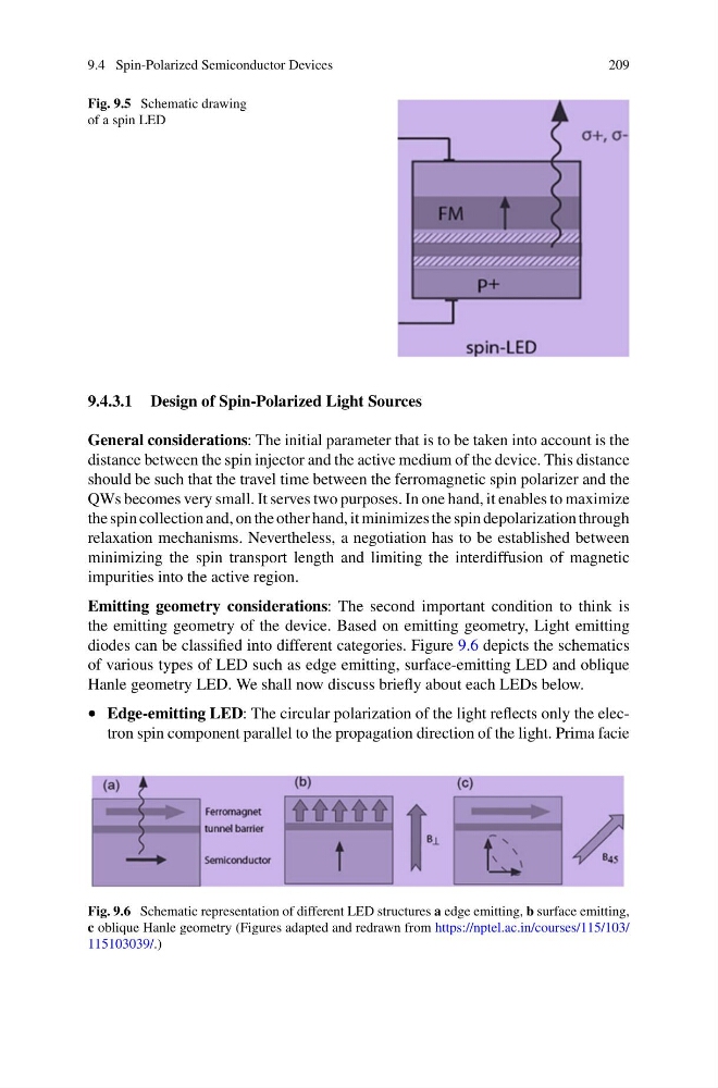
Fig. 9.5 Schematic drawing
of a spin LED
9.4.3.1 Design of Spin-Polarized Light Sources
General considerations: The initial parameter that is to be taken into account is the
distance between the spin injector and the active medium of the device. This distance
should be such that the travel time between the ferromagnetic spin polarizer and the
QWs becomes very small. It serves two purposes. In one hand, it enables to maximize
the spin collection and, on the other hand, it minimizes the spin depolarization through
relaxation mechanisms. Nevertheless, a negotiation has to be established between
minimizing the spin transport length and limiting the interdiffusion of magnetic
impurities into the active region.
Emitting geometry considerations: The second important condition to think is
the emitting geometry of the device. Based on emitting geometry, Light emitting
diodes can be classified into different categories. Figure 9.6 depicts the schematics
of various types of LED such as edge emitting, surface-emitting LED and oblique
Hanle geometry LED. We shall now discuss briefly about each LEDs below.
• Edge-emitting LED: The circular polarization of the light reflects only the electron spin component parallel to the propagation direction of the light. Prima facie
Fig. 9.6 Schematic representation of different LED structures a edge emitting, b surface emitting,
c oblique Hanle geometry (Figures adapted and redrawn from https://nptel.ac.in/courses/115/103/
115103039/.)
209
Fig. 9.5 Schematic drawing
of a spin LED
9.4.3.1 Design of Spin-Polarized Light Sources
General considerations: The initial parameter that is to be taken into account is the
distance between the spin injector and the active medium of the device. This distance
should be such that the travel time between the ferromagnetic spin polarizer and the
QWs becomes very small. It serves two purposes. In one hand, it enables to maximize
the spin collection and, on the other hand, it minimizes the spin depolarization through
relaxation mechanisms. Nevertheless, a negotiation has to be established between
minimizing the spin transport length and limiting the interdiffusion of magnetic
impurities into the active region.
Emitting geometry considerations: The second important condition to think is
the emitting geometry of the device. Based on emitting geometry, Light emitting
diodes can be classified into different categories. Figure 9.6 depicts the schematics
of various types of LED such as edge emitting, surface-emitting LED and oblique
Hanle geometry LED. We shall now discuss briefly about each LEDs below.
• Edge-emitting LED: The circular polarization of the light reflects only the electron spin component parallel to the propagation direction of the light. Prima facie
Fig. 9.6 Schematic representation of different LED structures a edge emitting, b surface emitting,
c oblique Hanle geometry (Figures adapted and redrawn from https://nptel.ac.in/courses/115/103/
115103039/.)