

208
9 Semiconductor Spintronics
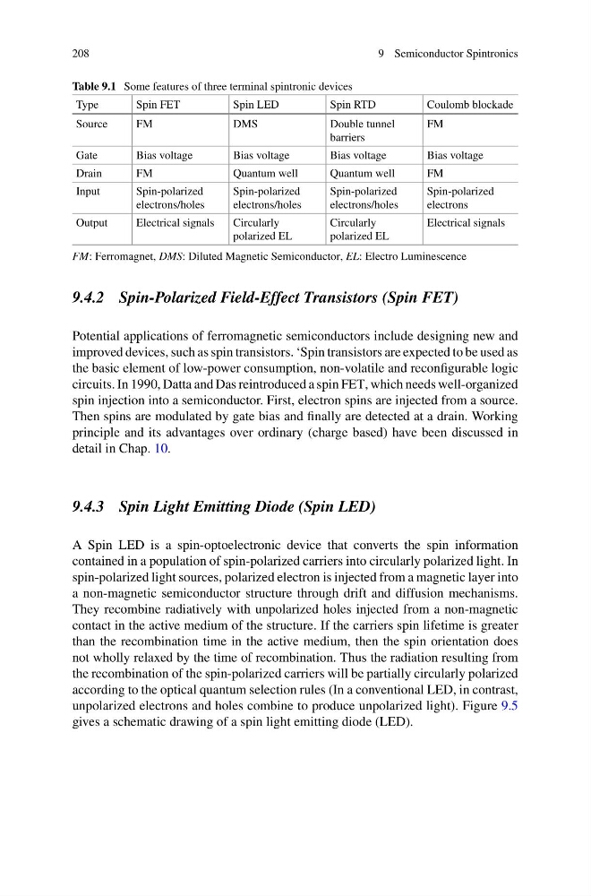
Table 9.1 Some features of three terminal spintronic devices
Type
Spin FET
Spin LED
Spin RTD
Coulomb blockade
Source
FM
DMS
Double tunnel
barriers
FM
Gate
Bias voltage
Bias voltage
Bias voltage
Bias voltage
Drain
FM
Quantum well
Quantum well
FM
Input
Spin-polarized
electrons/holes
Spin-polarized
electrons/holes
Spin-polarized
electrons/holes
Spin-polarized
electrons
Output
Electrical signals
Circularly
polarized EL
Circularly
polarized EL
Electrical signals
FM: Ferromagnet, DMS: Diluted Magnetic Semiconductor, EL: Electro Luminescence
9.4.2 Spin-Polarized Field-Effect Transistors (Spin FET)
Potential applications of ferromagnetic semiconductors include designing new and
improved devices, such as spin transistors. ‘Spin transistors are expected to be used as
the basic element of low-power consumption, non-volatile and reconfigurable logic
circuits. In 1990, Datta and Das reintroduced a spin FET, which needs well-organized
spin injection into a semiconductor. First, electron spins are injected from a source.
Then spins are modulated by gate bias and finally are detected at a drain. Working
principle and its advantages over ordinary (charge based) have been discussed in
detail in Chap. 10.
9.4.3 Spin Light Emitting Diode (Spin LED)
A Spin LED is a spin-optoelectronic device that converts the spin information
contained in a population of spin-polarized carriers into circularly polarized light. In
spin-polarized light sources, polarized electron is injected from a magnetic layer into
a non-magnetic semiconductor structure through drift and diffusion mechanisms.
They recombine radiatively with unpolarized holes injected from a non-magnetic
contact in the active medium of the structure. If the carriers spin lifetime is greater
than the recombination time in the active medium, then the spin orientation does
not wholly relaxed by the time of recombination. Thus the radiation resulting from
the recombination of the spin-polarized carriers will be partially circularly polarized
according to the optical quantum selection rules (In a conventional LED, in contrast,
unpolarized electrons and holes combine to produce unpolarized light). Figure 9.5
gives a schematic drawing of a spin light emitting diode (LED).
9 Semiconductor Spintronics
Table 9.1 Some features of three terminal spintronic devices
Type
Spin FET
Spin LED
Spin RTD
Coulomb blockade
Source
FM
DMS
Double tunnel
barriers
FM
Gate
Bias voltage
Bias voltage
Bias voltage
Bias voltage
Drain
FM
Quantum well
Quantum well
FM
Input
Spin-polarized
electrons/holes
Spin-polarized
electrons/holes
Spin-polarized
electrons/holes
Spin-polarized
electrons
Output
Electrical signals
Circularly
polarized EL
Circularly
polarized EL
Electrical signals
FM: Ferromagnet, DMS: Diluted Magnetic Semiconductor, EL: Electro Luminescence
9.4.2 Spin-Polarized Field-Effect Transistors (Spin FET)
Potential applications of ferromagnetic semiconductors include designing new and
improved devices, such as spin transistors. ‘Spin transistors are expected to be used as
the basic element of low-power consumption, non-volatile and reconfigurable logic
circuits. In 1990, Datta and Das reintroduced a spin FET, which needs well-organized
spin injection into a semiconductor. First, electron spins are injected from a source.
Then spins are modulated by gate bias and finally are detected at a drain. Working
principle and its advantages over ordinary (charge based) have been discussed in
detail in Chap. 10.
9.4.3 Spin Light Emitting Diode (Spin LED)
A Spin LED is a spin-optoelectronic device that converts the spin information
contained in a population of spin-polarized carriers into circularly polarized light. In
spin-polarized light sources, polarized electron is injected from a magnetic layer into
a non-magnetic semiconductor structure through drift and diffusion mechanisms.
They recombine radiatively with unpolarized holes injected from a non-magnetic
contact in the active medium of the structure. If the carriers spin lifetime is greater
than the recombination time in the active medium, then the spin orientation does
not wholly relaxed by the time of recombination. Thus the radiation resulting from
the recombination of the spin-polarized carriers will be partially circularly polarized
according to the optical quantum selection rules (In a conventional LED, in contrast,
unpolarized electrons and holes combine to produce unpolarized light). Figure 9.5
gives a schematic drawing of a spin light emitting diode (LED).