

8.5 Spintronic Terahertz Emitter (STE)
193
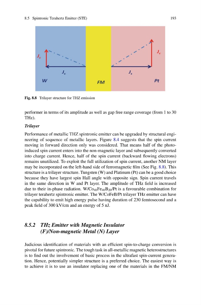
Fig. 8.8 Trilayer structure for THZ emission
performer in terms of its amplitude as well as gap free range coverage (from 1 to 30
THz).
Trilayer
Performance of metallic THZ spintronic emitter can be upgraded by structural engineering of sequence of metallic layers. Figure 8.4 suggests that the spin current
moving in forward direction only was considered. That means half of the photoinduced spin current enters into the non-magnetic layer and subsequently converted
into charge current. Hence, half of the spin current (backward flowing electrons)
remains unutilized. To exploit the full utilization of spin current, another NM layer
may be incorporated on the left-hand side of ferromagnetic film (See Fig. 8.8). This
structure is a trilayer structure. Tungsten (W) and Platinum (Pt) can be a good choice
because they have largest spin Hall angle with opposite sign. Spin current travels
in the same direction in W and Pt layer. The amplitude of THz field is increased
due to their in-phase radiation. W/Co 40 Fe 40 B 20 /Pt is a favourable combination for
trilayer terahertz spintronic emitter. The W/CoFeB/Pt trilayer THz emitter can have
the capability to emit high energy pulse having duration of 230 femtosecond and a
peak field of 300 kV/cm and an energy of 5 nJ.
8.5.2 THz Emitter with Magnetic Insulator
(F)/Non-magnetic Metal (N) Layer
Judicious identification of materials with an efficient spin-to-charge conversion is
pivotal for future spintronic. The tough task in all-metallic magnetic heterostructures
is to find out the involvement of basic process in the ultrafast spin-current generation. Hence, potentially simpler structure is a preferred choice. The easiest way is
to achieve it is to use an insulator replacing one of the materials in the FM/NM
193
Fig. 8.8 Trilayer structure for THZ emission
performer in terms of its amplitude as well as gap free range coverage (from 1 to 30
THz).
Trilayer
Performance of metallic THZ spintronic emitter can be upgraded by structural engineering of sequence of metallic layers. Figure 8.4 suggests that the spin current
moving in forward direction only was considered. That means half of the photoinduced spin current enters into the non-magnetic layer and subsequently converted
into charge current. Hence, half of the spin current (backward flowing electrons)
remains unutilized. To exploit the full utilization of spin current, another NM layer
may be incorporated on the left-hand side of ferromagnetic film (See Fig. 8.8). This
structure is a trilayer structure. Tungsten (W) and Platinum (Pt) can be a good choice
because they have largest spin Hall angle with opposite sign. Spin current travels
in the same direction in W and Pt layer. The amplitude of THz field is increased
due to their in-phase radiation. W/Co 40 Fe 40 B 20 /Pt is a favourable combination for
trilayer terahertz spintronic emitter. The W/CoFeB/Pt trilayer THz emitter can have
the capability to emit high energy pulse having duration of 230 femtosecond and a
peak field of 300 kV/cm and an energy of 5 nJ.
8.5.2 THz Emitter with Magnetic Insulator
(F)/Non-magnetic Metal (N) Layer
Judicious identification of materials with an efficient spin-to-charge conversion is
pivotal for future spintronic. The tough task in all-metallic magnetic heterostructures
is to find out the involvement of basic process in the ultrafast spin-current generation. Hence, potentially simpler structure is a preferred choice. The easiest way is
to achieve it is to use an insulator replacing one of the materials in the FM/NM