

140
5 Spin-Transfer Torque
where
e 1 = (cos φ sin θ, sin φ sin θ, cos θ) and
e 2 = (0, 0, 1) are unit vectors along
the direction of angular momentum of FM1 and FM2 layers, respectively. It is noteworthy that for
S 1 the expectation values of the Pauli spin matrices, i.e., σ x , σ y , σ z ,
are cos φ sin θ, sin φ sin θ, cos θ. J
Q is the charge current and
J
Q
−e
corresponds to
the number of electrons flowing per unit time. g(θ ) represents the efficiency of
spin-transfer process. Moreover, g(θ ) has been found to be dependent on the spin
polarization (P) of the conduction electrons flowing through the ferromagnetic layers
and on the relative angle, θ between
S 1 and
S 2 . Slonczewski (1996) has proposed a
formula for this parameter g(θ ) by considering a free electron model. The formula
is suitable for the CPP-GMR junctions as follows:
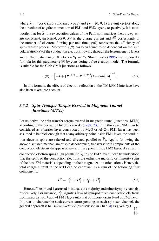
g(θ ) =
−4 +
P
−1/2
+ P
+1/2
3 (3 + cosθ )/4
−1 .
(5.7)
In this formula, the effects of electron reflection at the NM1/FM2 interface have
also been taken into account.
5.5.2 Spin-Transfer Torque Exerted in Magnetic Tunnel
Junctions (MTJs)
Let us derive the spin-transfer torque exerted in magnetic tunnel junctions (MTJs)
according to the derivation by Slonczewski (1989, 2005). In this case, NM1 can be
considered as a barrier layer constructed by MgO or Al 2 O 3 . FM1 layer has been
assumed to be thick enough that at any arbitrary point inside FM1 layer, the conduction electron spins are relaxed and directed parallel to
S 1 . Again, following the
above discussed mechanism of spin decoherence, transverse spin components of the
conduction electrons disappear at any arbitrary point inside FM2 layer. As a result,
conduction electron spins align parallel to
S 2 inside FM2 layer. It can be understood
that the spins of the conduction electrons are either the majority or minority spins
of the host FM materials depending on their magnetization orientations. Hence, the
total charge current in the MTJ can be expressed as a sum of the following four
components:
J
Q
= J
Q
↑↑ + J
Q
↑↓ + J
Q
↓↑ + J
Q
↓↓ .
(5.8)
Here, suffixes ↑ and ↓ are used to indicate the majority and minority spin channels,
respectively. For instance, J
Q
↑↓ signifies flow of spin-polarized conduction electrons
from majority spin band of FM1 layer into that of minority spin band of FM2 layer.
In order to characterize such current corresponding to each spin sub-channel, the
general approach is to use conductance (as discussed in Chap. 4) as given by G ↑↑
↓↓
.
5 Spin-Transfer Torque
where
e 1 = (cos φ sin θ, sin φ sin θ, cos θ) and
e 2 = (0, 0, 1) are unit vectors along
the direction of angular momentum of FM1 and FM2 layers, respectively. It is noteworthy that for
S 1 the expectation values of the Pauli spin matrices, i.e., σ x , σ y , σ z ,
are cos φ sin θ, sin φ sin θ, cos θ. J
Q is the charge current and
J
Q
−e
corresponds to
the number of electrons flowing per unit time. g(θ ) represents the efficiency of
spin-transfer process. Moreover, g(θ ) has been found to be dependent on the spin
polarization (P) of the conduction electrons flowing through the ferromagnetic layers
and on the relative angle, θ between
S 1 and
S 2 . Slonczewski (1996) has proposed a
formula for this parameter g(θ ) by considering a free electron model. The formula
is suitable for the CPP-GMR junctions as follows:
g(θ ) =
−4 +
P
−1/2
+ P
+1/2
3 (3 + cosθ )/4
−1 .
(5.7)
In this formula, the effects of electron reflection at the NM1/FM2 interface have
also been taken into account.
5.5.2 Spin-Transfer Torque Exerted in Magnetic Tunnel
Junctions (MTJs)
Let us derive the spin-transfer torque exerted in magnetic tunnel junctions (MTJs)
according to the derivation by Slonczewski (1989, 2005). In this case, NM1 can be
considered as a barrier layer constructed by MgO or Al 2 O 3 . FM1 layer has been
assumed to be thick enough that at any arbitrary point inside FM1 layer, the conduction electron spins are relaxed and directed parallel to
S 1 . Again, following the
above discussed mechanism of spin decoherence, transverse spin components of the
conduction electrons disappear at any arbitrary point inside FM2 layer. As a result,
conduction electron spins align parallel to
S 2 inside FM2 layer. It can be understood
that the spins of the conduction electrons are either the majority or minority spins
of the host FM materials depending on their magnetization orientations. Hence, the
total charge current in the MTJ can be expressed as a sum of the following four
components:
J
Q
= J
Q
↑↑ + J
Q
↑↓ + J
Q
↓↑ + J
Q
↓↓ .
(5.8)
Here, suffixes ↑ and ↓ are used to indicate the majority and minority spin channels,
respectively. For instance, J
Q
↑↓ signifies flow of spin-polarized conduction electrons
from majority spin band of FM1 layer into that of minority spin band of FM2 layer.
In order to characterize such current corresponding to each spin sub-channel, the
general approach is to use conductance (as discussed in Chap. 4) as given by G ↑↑
↓↓
.