

5.5 Spin-Transfer Torque in Magnetic Multilayer Nanopillar
141
Let us now suppose that V is the applied voltage and the form of the spin wave
functions in the FM1 layer is given by
wavefunctions corresponding to majority spin electrons: cos(θ/2)|↑↑ + sin(θ/2)|↓↓;
wavefunctions corresponding to minority spin electrons: sin(θ/2)|↑↑ − cos(θ/2)|↓↓.
(5.9)
On the other hand, majority and minority spin wavefunctions in the FM2 layer
are given by |↑↑ and |↓↓ , respectively. Therefore, currents can be expressed as
J
Q
↑↑
↓↓
= V G ↑↑
↓↓
cos
2 θ
2
J
Q
↓↑
↑↓
= V G ↓↑
↑↓
sin
2 θ
2
.
(5.10)
Thus, spin currents at any two arbitrary points at FM1 and FM2 layers can be
obtained as
J
S
1 =
2
1
−e
J
Q
↑↑ + J
Q
↑↓ − J
Q
↓↑ − J
Q
↓↓
e 1
J
S
2 =
2
1
−e
J
Q
↑↑ − J
Q
↑↓ + J
Q
↓↑ − J
Q
↓↓
e 2 .
(5.11)
Therefore, total current is obtained as follows:
J
Q
=
1
2
V
G ↑↑ + G ↓↓ + G ↑↓ + G ↓↑
+
G ↑↑ + G ↓↓ − G ↑↓ − G ↓↑
e 2 .
e 1
.
(5.12)
Therefore, total spin-transfer torqueis obtained as follows:
d
S 2
dt
=
2
1
−e
1
2
V
G ↑↑ − G ↓↓
+
G ↑↓ − G ↓↑
e 2 ×
e 1 ×
e 2
.
(5.13)
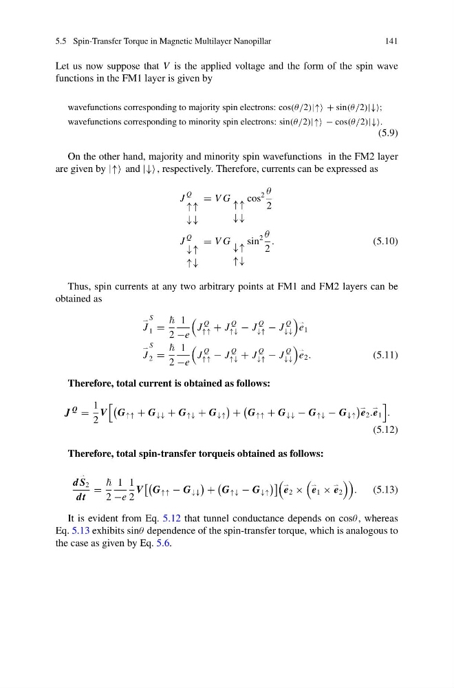
It is evident from Eq. 5.12 that tunnel conductance depends on cosθ , whereas
Eq. 5.13 exhibits sinθ dependence of the spin-transfer torque, which is analogous to
the case as given by Eq. 5.6.
141
Let us now suppose that V is the applied voltage and the form of the spin wave
functions in the FM1 layer is given by
wavefunctions corresponding to majority spin electrons: cos(θ/2)|↑↑ + sin(θ/2)|↓↓;
wavefunctions corresponding to minority spin electrons: sin(θ/2)|↑↑ − cos(θ/2)|↓↓.
(5.9)
On the other hand, majority and minority spin wavefunctions in the FM2 layer
are given by |↑↑ and |↓↓ , respectively. Therefore, currents can be expressed as
J
Q
↑↑
↓↓
= V G ↑↑
↓↓
cos
2 θ
2
J
Q
↓↑
↑↓
= V G ↓↑
↑↓
sin
2 θ
2
.
(5.10)
Thus, spin currents at any two arbitrary points at FM1 and FM2 layers can be
obtained as
J
S
1 =
2
1
−e
J
Q
↑↑ + J
Q
↑↓ − J
Q
↓↑ − J
Q
↓↓
e 1
J
S
2 =
2
1
−e
J
Q
↑↑ − J
Q
↑↓ + J
Q
↓↑ − J
Q
↓↓
e 2 .
(5.11)
Therefore, total current is obtained as follows:
J
Q
=
1
2
V
G ↑↑ + G ↓↓ + G ↑↓ + G ↓↑
+
G ↑↑ + G ↓↓ − G ↑↓ − G ↓↑
e 2 .
e 1
.
(5.12)
Therefore, total spin-transfer torqueis obtained as follows:
d
S 2
dt
=
2
1
−e
1
2
V
G ↑↑ − G ↓↓
+
G ↑↓ − G ↓↑
e 2 ×
e 1 ×
e 2
.
(5.13)
It is evident from Eq. 5.12 that tunnel conductance depends on cosθ , whereas
Eq. 5.13 exhibits sinθ dependence of the spin-transfer torque, which is analogous to
the case as given by Eq. 5.6.