

5.5 Spin-Transfer Torque in Magnetic Multilayer Nanopillar
139
Subsequently, these spin-polarized electrons are injected into the adjacent NM1 layer.
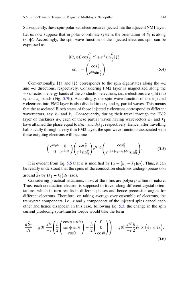
Let us now suppose that in polar coordinate system, the orientation of
S 1 is along
(θ, φ). Accordingly, the spin wave function of the injected electrons spin can be
expressed as
|(θ, φ) cos
θ
2
|↑↑+ e
iφ sin
θ
2
|↓↓
or, =
cos
θ
2
e iφ sin
θ
2
.
(5.4)
Conventionally, |↑↑ and |↓↓ corresponds to the spin eigenstates along the +z
and −z directions, respectively. Considering FM2 layer is magnetized along the
+z direction, energy bands of the conduction electrons, i.e., s-electrons are split into
s ↑ and s ↓ bands (Fig. 5.7b). Accordingly, the spin wave function of the injected
s-electrons into FM2 layer is also divided into s ↑ and s ↓ partial waves. This means
that the associated Bloch states of those injected s-electrons correspond to different
wavevectors, say, k ↑ and k ↓ . Consequently, during their travel through the FM2
layer of thickness d 2 , each of these partial waves having wavevectors k ↑ and k ↓
have attained the phase equal to d 2 k ↑ and d 2 k ↓ , respectively. Hence, after travelling
ballistically through a very thin FM2 layer, the spin wave functions associated with
these outgoing electrons will become
e
ik ↑ d 2
0
0 e
ik ↓ d 2
cos
θ
2
e iφ sin
θ
2
e
ik ↑ d 2
cos
θ
2
e
i(φ+(k ↓ −k ↑ )d2) sin
θ
2
.
(5.5)
It is evident from Eq. 5.5 that φ is modified by
φ +
k ↓ − k ↑
d 2
. Thus, it can
be readily understood that the spins of the conduction electrons undergo precession
around
S 2 by
k ↓ − k ↑
d 2 (rad).
Considering practical situations, most of the films are polycrystalline in nature.
Thus, each conduction electron is supposed to travel along different crystal orientations, which in turn results in different phases and hence precession angles for
different electrons. Therefore, on taking average over ensemble of electrons, the
transverse components, i.e., x and y components of the injected spins cancel each
other and hence disappear. In this case, following Eq. 5.3, the change in the spin
current producing spin-transfer torque would take the form
d
S 2
dt
= g(θ)
J
Q
−e
⎛
⎝
2
⎛
⎝
cos φ sin θ
sin φ sin θ
cosθ
⎞
⎠ −
2
⎛
⎝
0
0
cosθ
⎞
⎠
⎞
⎠ = g(θ)
J
Q
−e
2
e 2 ×
e 1 ×
e 2
,
(5.6)
139
Subsequently, these spin-polarized electrons are injected into the adjacent NM1 layer.
Let us now suppose that in polar coordinate system, the orientation of
S 1 is along
(θ, φ). Accordingly, the spin wave function of the injected electrons spin can be
expressed as
|(θ, φ) cos
θ
2
|↑↑+ e
iφ sin
θ
2
|↓↓
or, =
cos
θ
2
e iφ sin
θ
2
.
(5.4)
Conventionally, |↑↑ and |↓↓ corresponds to the spin eigenstates along the +z
and −z directions, respectively. Considering FM2 layer is magnetized along the
+z direction, energy bands of the conduction electrons, i.e., s-electrons are split into
s ↑ and s ↓ bands (Fig. 5.7b). Accordingly, the spin wave function of the injected
s-electrons into FM2 layer is also divided into s ↑ and s ↓ partial waves. This means
that the associated Bloch states of those injected s-electrons correspond to different
wavevectors, say, k ↑ and k ↓ . Consequently, during their travel through the FM2
layer of thickness d 2 , each of these partial waves having wavevectors k ↑ and k ↓
have attained the phase equal to d 2 k ↑ and d 2 k ↓ , respectively. Hence, after travelling
ballistically through a very thin FM2 layer, the spin wave functions associated with
these outgoing electrons will become
e
ik ↑ d 2
0
0 e
ik ↓ d 2
cos
θ
2
e iφ sin
θ
2
e
ik ↑ d 2
cos
θ
2
e
i(φ+(k ↓ −k ↑ )d2) sin
θ
2
.
(5.5)
It is evident from Eq. 5.5 that φ is modified by
φ +
k ↓ − k ↑
d 2
. Thus, it can
be readily understood that the spins of the conduction electrons undergo precession
around
S 2 by
k ↓ − k ↑
d 2 (rad).
Considering practical situations, most of the films are polycrystalline in nature.
Thus, each conduction electron is supposed to travel along different crystal orientations, which in turn results in different phases and hence precession angles for
different electrons. Therefore, on taking average over ensemble of electrons, the
transverse components, i.e., x and y components of the injected spins cancel each
other and hence disappear. In this case, following Eq. 5.3, the change in the spin
current producing spin-transfer torque would take the form
d
S 2
dt
= g(θ)
J
Q
−e
⎛
⎝
2
⎛
⎝
cos φ sin θ
sin φ sin θ
cosθ
⎞
⎠ −
2
⎛
⎝
0
0
cosθ
⎞
⎠
⎞
⎠ = g(θ)
J
Q
−e
2
e 2 ×
e 1 ×
e 2
,
(5.6)