

138
5 Spin-Transfer Torque
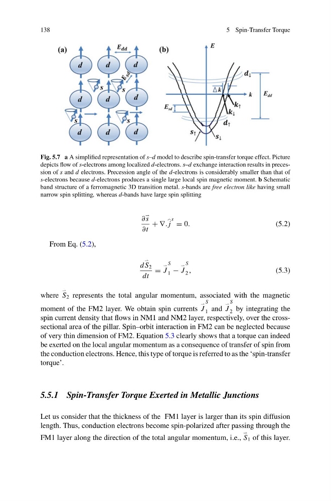
Fig. 5.7 a A simplified representation of s–d model to describe spin-transfer torque effect. Picture
depicts flow of s-electrons among localized d-electrons. s–d exchange interaction results in precession of s and d electrons. Precession angle of the d-electrons is considerably smaller than that of
s-electrons because d-electrons produces a single large local spin magnetic moment. b Schematic
band structure of a ferromagnetic 3D transition metal. s-bands are free electron like having small
narrow spin splitting, whereas d-bands have large spin splitting
∂
s
∂t
+ ∇. j
s = 0.
(5.2)
From Eq. (5.2),
d
S 2
dt
=
J
S
1 −
J
S
2 ,
(5.3)
where
S 2 represents the total angular momentum, associated with the magnetic
moment of the FM2 layer. We obtain spin currents
J
S
1 and
J
S
2 by integrating the
spin current density that flows in NM1 and NM2 layer, respectively, over the crosssectional area of the pillar. Spin–orbit interaction in FM2 can be neglected because
of very thin dimension of FM2. Equation 5.3 clearly shows that a torque can indeed
be exerted on the local angular momentum as a consequence of transfer of spin from
the conduction electrons. Hence, this type of torque is referred to as the ‘spin-transfer
torque’.
5.5.1 Spin-Transfer Torque Exerted in Metallic Junctions
Let us consider that the thickness of the FM1 layer is larger than its spin diffusion
length. Thus, conduction electrons become spin-polarized after passing through the
FM1 layer along the direction of the total angular momentum, i.e.,
S 1 of this layer.
5 Spin-Transfer Torque
Fig. 5.7 a A simplified representation of s–d model to describe spin-transfer torque effect. Picture
depicts flow of s-electrons among localized d-electrons. s–d exchange interaction results in precession of s and d electrons. Precession angle of the d-electrons is considerably smaller than that of
s-electrons because d-electrons produces a single large local spin magnetic moment. b Schematic
band structure of a ferromagnetic 3D transition metal. s-bands are free electron like having small
narrow spin splitting, whereas d-bands have large spin splitting
∂
s
∂t
+ ∇. j
s = 0.
(5.2)
From Eq. (5.2),
d
S 2
dt
=
J
S
1 −
J
S
2 ,
(5.3)
where
S 2 represents the total angular momentum, associated with the magnetic
moment of the FM2 layer. We obtain spin currents
J
S
1 and
J
S
2 by integrating the
spin current density that flows in NM1 and NM2 layer, respectively, over the crosssectional area of the pillar. Spin–orbit interaction in FM2 can be neglected because
of very thin dimension of FM2. Equation 5.3 clearly shows that a torque can indeed
be exerted on the local angular momentum as a consequence of transfer of spin from
the conduction electrons. Hence, this type of torque is referred to as the ‘spin-transfer
torque’.
5.5.1 Spin-Transfer Torque Exerted in Metallic Junctions
Let us consider that the thickness of the FM1 layer is larger than its spin diffusion
length. Thus, conduction electrons become spin-polarized after passing through the
FM1 layer along the direction of the total angular momentum, i.e.,
S 1 of this layer.