

84
3 Giant Magnetoresistance (GMR)
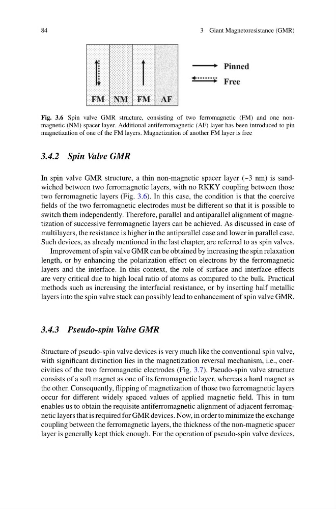
Fig. 3.6 Spin valve GMR structure, consisting of two ferromagnetic (FM) and one nonmagnetic (NM) spacer layer. Additional antiferromagnetic (AF) layer has been introduced to pin
magnetization of one of the FM layers. Magnetization of another FM layer is free
3.4.2 Spin Valve GMR
In spin valve GMR structure, a thin non-magnetic spacer layer (~3 nm) is sandwiched between two ferromagnetic layers, with no RKKY coupling between those
two ferromagnetic layers (Fig. 3.6). In this case, the condition is that the coercive
fields of the two ferromagnetic electrodes must be different so that it is possible to
switch them independently. Therefore, parallel and antiparallel alignment of magnetization of successive ferromagnetic layers can be achieved. As discussed in case of
multilayers, the resistance is higher in the antiparallel case and lower in parallel case.
Such devices, as already mentioned in the last chapter, are referred to as spin valves.
Improvement of spin valve GMR can be obtained by increasing the spin relaxation
length, or by enhancing the polarization effect on electrons by the ferromagnetic
layers and the interface. In this context, the role of surface and interface effects
are very critical due to high local ratio of atoms as compared to the bulk. Practical
methods such as increasing the interfacial resistance, or by inserting half metallic
layers into the spin valve stack can possibly lead to enhancement of spin valve GMR.
3.4.3 Pseudo-spin Valve GMR
Structure of pseudo-spin valve devices is very much like the conventional spin valve,
with significant distinction lies in the magnetization reversal mechanism, i.e., coercivities of the two ferromagnetic electrodes (Fig. 3.7). Pseudo-spin valve structure
consists of a soft magnet as one of its ferromagnetic layer, whereas a hard magnet as
the other. Consequently, flipping of magnetization of those two ferromagnetic layers
occur for different widely spaced values of applied magnetic field. This in turn
enables us to obtain the requisite antiferromagnetic alignment of adjacent ferromagnetic layers that is required for GMR devices. Now, in order to minimize the exchange
coupling between the ferromagnetic layers, the thickness of the non-magnetic spacer
layer is generally kept thick enough. For the operation of pseudo-spin valve devices,
3 Giant Magnetoresistance (GMR)
Fig. 3.6 Spin valve GMR structure, consisting of two ferromagnetic (FM) and one nonmagnetic (NM) spacer layer. Additional antiferromagnetic (AF) layer has been introduced to pin
magnetization of one of the FM layers. Magnetization of another FM layer is free
3.4.2 Spin Valve GMR
In spin valve GMR structure, a thin non-magnetic spacer layer (~3 nm) is sandwiched between two ferromagnetic layers, with no RKKY coupling between those
two ferromagnetic layers (Fig. 3.6). In this case, the condition is that the coercive
fields of the two ferromagnetic electrodes must be different so that it is possible to
switch them independently. Therefore, parallel and antiparallel alignment of magnetization of successive ferromagnetic layers can be achieved. As discussed in case of
multilayers, the resistance is higher in the antiparallel case and lower in parallel case.
Such devices, as already mentioned in the last chapter, are referred to as spin valves.
Improvement of spin valve GMR can be obtained by increasing the spin relaxation
length, or by enhancing the polarization effect on electrons by the ferromagnetic
layers and the interface. In this context, the role of surface and interface effects
are very critical due to high local ratio of atoms as compared to the bulk. Practical
methods such as increasing the interfacial resistance, or by inserting half metallic
layers into the spin valve stack can possibly lead to enhancement of spin valve GMR.
3.4.3 Pseudo-spin Valve GMR
Structure of pseudo-spin valve devices is very much like the conventional spin valve,
with significant distinction lies in the magnetization reversal mechanism, i.e., coercivities of the two ferromagnetic electrodes (Fig. 3.7). Pseudo-spin valve structure
consists of a soft magnet as one of its ferromagnetic layer, whereas a hard magnet as
the other. Consequently, flipping of magnetization of those two ferromagnetic layers
occur for different widely spaced values of applied magnetic field. This in turn
enables us to obtain the requisite antiferromagnetic alignment of adjacent ferromagnetic layers that is required for GMR devices. Now, in order to minimize the exchange
coupling between the ferromagnetic layers, the thickness of the non-magnetic spacer
layer is generally kept thick enough. For the operation of pseudo-spin valve devices,