

4. Open the CT acquisition software, create a new patient, and
identify each sample with an ID number, the name of the
solution, and date. Make a topogram, and select the region of
interest to image, where your sample is located. Try to select
the shortest possible length in order to get a single rotation of
the CT gantry; this way the acquisition time will be lower (see
Note 7). Make sure the thermocouple is out of the area to
image.
5. Select the following acquisition parameters: 360 projections,
pitch 1, ultra-fine frame resolution, 500 ms of exposure time,
and 75 kV of the X-ray tube voltage. The total time of the
image acquisition will depend on these parameters and on the
length of the sample to image (see Note 8).
N 2 gas
input tubes
3 N 2 gas
output
2 Insulating
container
140 mm
Ovarian tissue sample 8
7 Cryovial
3
9 Sample
holder
80 mm
45 mm
45 mm
10 mm
15 mm
20 mm
58 mm
1
3
1
200 µL Microplate
(A)
(B)
(C)
(D)
1
4
5 50 mL Vial
6 Kidney sample
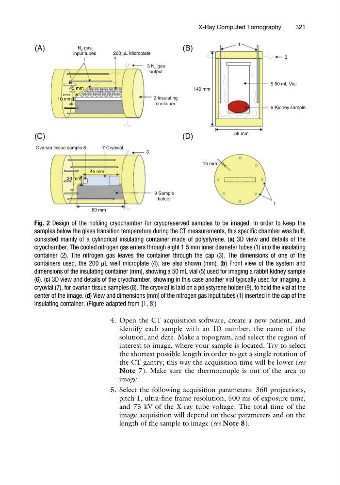
Fig. 2 Design of the holding cryochamber for cryopreserved samples to be imaged. In order to keep the
samples below the glass transition temperature during the CT measurements, this specific chamber was built,
consisted mainly of a cylindrical insulating container made of polystyrene. (a) 3D view and details of the
cryochamber. The cooled nitrogen gas enters through eight 1.5 mm inner diameter tubes (1) into the insulating
container (2). The nitrogen gas leaves the container through the cap (3). The dimensions of one of the
containers used, the 200 μL well microplate (4), are also shown (mm). (b) Front view of the system and
dimensions of the insulating container (mm), showing a 50 mL vial (5) used for imaging a rabbit kidney sample
(6). (c) 3D view and details of the cryochamber, showing in this case another vial typically used for imaging, a
cryovial (7), for ovarian tissue samples (8). The cryovial is laid on a polystyrene holder (9), to hold the vial at the
center of the image. (d) View and dimensions (mm) of the nitrogen gas input tubes (1) inserted in the cap of the
insulating container. (Figure adapted from [1, 8])
X-Ray Computed Tomography
321
identify each sample with an ID number, the name of the
solution, and date. Make a topogram, and select the region of
interest to image, where your sample is located. Try to select
the shortest possible length in order to get a single rotation of
the CT gantry; this way the acquisition time will be lower (see
Note 7). Make sure the thermocouple is out of the area to
image.
5. Select the following acquisition parameters: 360 projections,
pitch 1, ultra-fine frame resolution, 500 ms of exposure time,
and 75 kV of the X-ray tube voltage. The total time of the
image acquisition will depend on these parameters and on the
length of the sample to image (see Note 8).
N 2 gas
input tubes
3 N 2 gas
output
2 Insulating
container
140 mm
Ovarian tissue sample 8
7 Cryovial
3
9 Sample
holder
80 mm
45 mm
45 mm
10 mm
15 mm
20 mm
58 mm
1
3
1
200 µL Microplate
(A)
(B)
(C)
(D)
1
4
5 50 mL Vial
6 Kidney sample
Fig. 2 Design of the holding cryochamber for cryopreserved samples to be imaged. In order to keep the
samples below the glass transition temperature during the CT measurements, this specific chamber was built,
consisted mainly of a cylindrical insulating container made of polystyrene. (a) 3D view and details of the
cryochamber. The cooled nitrogen gas enters through eight 1.5 mm inner diameter tubes (1) into the insulating
container (2). The nitrogen gas leaves the container through the cap (3). The dimensions of one of the
containers used, the 200 μL well microplate (4), are also shown (mm). (b) Front view of the system and
dimensions of the insulating container (mm), showing a 50 mL vial (5) used for imaging a rabbit kidney sample
(6). (c) 3D view and details of the cryochamber, showing in this case another vial typically used for imaging, a
cryovial (7), for ovarian tissue samples (8). The cryovial is laid on a polystyrene holder (9), to hold the vial at the
center of the image. (d) View and dimensions (mm) of the nitrogen gas input tubes (1) inserted in the cap of the
insulating container. (Figure adapted from [1, 8])
X-Ray Computed Tomography
321