

64
Biomedical Signal and Image Processing
Before describing the Sobel mask for detecting vertical lines, an example of the
application of the horizontal Sobel mask mentioned earlier is provided that further
illustrates the concept of the Sobel edge detection.
Example 4.1
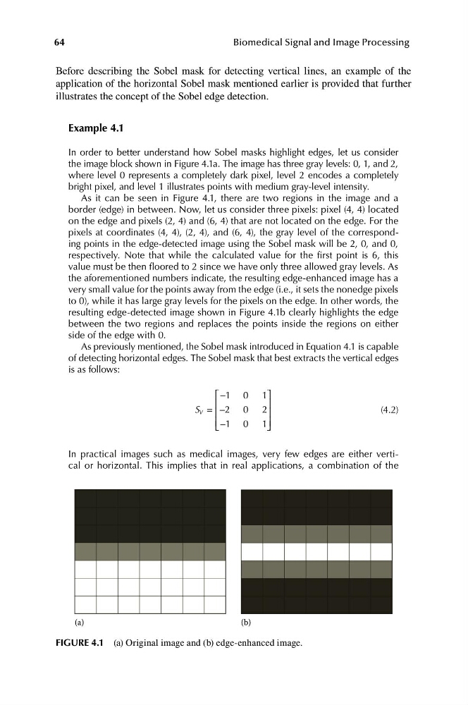
In order to better understand how Sobel masks highlight edges, let us consider
the image block shown in Figure 4.1a. The image has three gray levels: 0, 1, and 2,
where level 0 represents a completely dark pixel, level 2 encodes a completely
bright pixel, and level 1 illustrates points with medium gray-level intensity.
As it can be seen in Figure 4.1, there are two regions in the image and a
border (edge) in between. Now, let us consider three pixels: pixel (4, 4) located
on the edge and pixels (2, 4) and (6, 4) that are not located on the edge. For the
pixels at coordinates (4, 4), (2, 4), and (6, 4), the gray level of the corresponding points in the edge-detected image using the Sobel mask will be 2, 0, and 0,
respectively. Note that while the calculated value for the first point is 6, this
value must be then floored to 2 since we have only three allowed gray levels. As
the aforementioned numbers indicate, the resulting edge-enhanced image has a
very small value for the points away from the edge (i.e., it sets the nonedge pixels
to 0), while it has large gray levels for the pixels on the edge. In other words, the
resulting edge-detected image shown in Figure 4.1b clearly highlights the edge
between the two regions and replaces the points inside the regions on either
side of the edge with 0.
As previously mentioned, the Sobel mask introduced in Equation 4.1 is capable
of detecting horizontal edges. The Sobel mask that best extracts the vertical edges
is as follows:
⎡ −1 0 1⎤
⎢
⎥
S V = −2 0 2
⎢
⎥
(4.2)
⎢ ⎣ − 1 0 1 ⎥ ⎦
In practical images such as medical images, very few edges are either vertical or horizontal. This implies that in real applications, a combination of the
(a)
(b)
FIGURE 4.1 (a) Original image and (b) edge-enhanced image.
Biomedical Signal and Image Processing
Before describing the Sobel mask for detecting vertical lines, an example of the
application of the horizontal Sobel mask mentioned earlier is provided that further
illustrates the concept of the Sobel edge detection.
Example 4.1
In order to better understand how Sobel masks highlight edges, let us consider
the image block shown in Figure 4.1a. The image has three gray levels: 0, 1, and 2,
where level 0 represents a completely dark pixel, level 2 encodes a completely
bright pixel, and level 1 illustrates points with medium gray-level intensity.
As it can be seen in Figure 4.1, there are two regions in the image and a
border (edge) in between. Now, let us consider three pixels: pixel (4, 4) located
on the edge and pixels (2, 4) and (6, 4) that are not located on the edge. For the
pixels at coordinates (4, 4), (2, 4), and (6, 4), the gray level of the corresponding points in the edge-detected image using the Sobel mask will be 2, 0, and 0,
respectively. Note that while the calculated value for the first point is 6, this
value must be then floored to 2 since we have only three allowed gray levels. As
the aforementioned numbers indicate, the resulting edge-enhanced image has a
very small value for the points away from the edge (i.e., it sets the nonedge pixels
to 0), while it has large gray levels for the pixels on the edge. In other words, the
resulting edge-detected image shown in Figure 4.1b clearly highlights the edge
between the two regions and replaces the points inside the regions on either
side of the edge with 0.
As previously mentioned, the Sobel mask introduced in Equation 4.1 is capable
of detecting horizontal edges. The Sobel mask that best extracts the vertical edges
is as follows:
⎡ −1 0 1⎤
⎢
⎥
S V = −2 0 2
⎢
⎥
(4.2)
⎢ ⎣ − 1 0 1 ⎥ ⎦
In practical images such as medical images, very few edges are either vertical or horizontal. This implies that in real applications, a combination of the
(a)
(b)
FIGURE 4.1 (a) Original image and (b) edge-enhanced image.