

60
Biomedical Signal and Image Processing
u
v
D 0
|H|
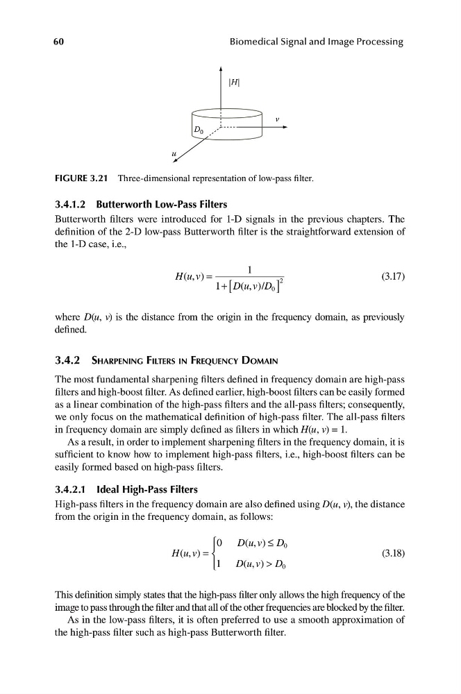
FIGURE 3.21 Three-dimensional representation of low-pass filter.
3.4.1.2 Butterworth Low-Pass Filters
Butterworth filters were introduced for 1-D signals in the previous chapters. The
definition of the 2-D low-pass Butterworth filter is the straightforward extension of
the 1-D case, i.e.,
1
H u v
( , ) =
2
(3.17)
1+ [ D u v D
( , ) / 0 ]
where D(u, v) is the distance from the origin in the frequency domain, as previously
defined.
3.4.2 SHARPENING FILTERS IN FREQUENCY DOMAIN
The most fundamental sharpening filters defined in frequency domain are high-pass
filters and high-boost filter. As defined earlier, high-boost filters can be easily formed
as a linear combination of the high-pass filters and the all-pass filters; consequently,
we only focus on the mathematical definition of high-pass filter. The all-pass filters
in frequency domain are simply defined as filters in which H(u, v) = 1.
As a result, in order to implement sharpening filters in the frequency domain, it is
sufficient to know how to implement high-pass filters, i.e., high-boost filters can be
easily formed based on high-pass filters.
3.4.2.1 Ideal High-Pass Filters
High-pass filters in the frequency domain are also defined using D(u, v), the distance
from the origin in the frequency domain, as follows:
D u v ≤ D 0
⎧0
( , )
⎪
H u v
( , ) = ⎨
(3.18)
⎩
D u v > D 0
⎪1
( , )
This definition simply states that the high-pass filter only allows the high frequency of the
image to pass through the filter and that all of the other frequencies are blocked by the filter.
As in the low-pass filters, it is often preferred to use a smooth approximation of
the high-pass filter such as high-pass Butterworth filter.
Biomedical Signal and Image Processing
u
v
D 0
|H|
FIGURE 3.21 Three-dimensional representation of low-pass filter.
3.4.1.2 Butterworth Low-Pass Filters
Butterworth filters were introduced for 1-D signals in the previous chapters. The
definition of the 2-D low-pass Butterworth filter is the straightforward extension of
the 1-D case, i.e.,
1
H u v
( , ) =
2
(3.17)
1+ [ D u v D
( , ) / 0 ]
where D(u, v) is the distance from the origin in the frequency domain, as previously
defined.
3.4.2 SHARPENING FILTERS IN FREQUENCY DOMAIN
The most fundamental sharpening filters defined in frequency domain are high-pass
filters and high-boost filter. As defined earlier, high-boost filters can be easily formed
as a linear combination of the high-pass filters and the all-pass filters; consequently,
we only focus on the mathematical definition of high-pass filter. The all-pass filters
in frequency domain are simply defined as filters in which H(u, v) = 1.
As a result, in order to implement sharpening filters in the frequency domain, it is
sufficient to know how to implement high-pass filters, i.e., high-boost filters can be
easily formed based on high-pass filters.
3.4.2.1 Ideal High-Pass Filters
High-pass filters in the frequency domain are also defined using D(u, v), the distance
from the origin in the frequency domain, as follows:
D u v ≤ D 0
⎧0
( , )
⎪
H u v
( , ) = ⎨
(3.18)
⎩
D u v > D 0
⎪1
( , )
This definition simply states that the high-pass filter only allows the high frequency of the
image to pass through the filter and that all of the other frequencies are blocked by the filter.
As in the low-pass filters, it is often preferred to use a smooth approximation of
the high-pass filter such as high-pass Butterworth filter.