

316
Biomedical Signal and Image Processing
incident upon the interface between the lung, which consists of air and soft tissue,
is reflected. Practically speaking, in order to create an image of a biological organ
using ultrasound, one needs to have a line of sight from the transducer to the tissue
without any bones or lungs in the path.
16.4.4 REFLECTION
The next concept to be discussed is reflection. During propagation, a sound wave often
moves through different media. At the interface between two acoustically different
media, the path of the sound wave can be significantly affected. Many secondary
waves will be generated, one of which is the reflected wave. The angle of reflection
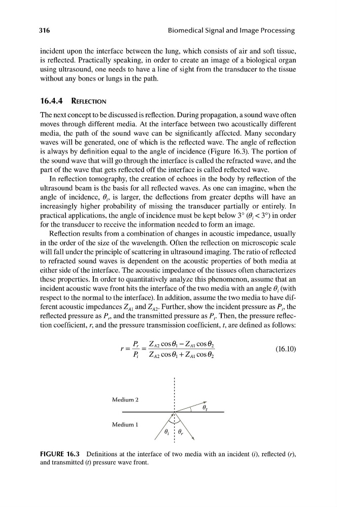
is always by definition equal to the angle of incidence (Figure 16.3). The portion of
the sound wave that will go through the interface is called the refracted wave, and the
part of the wave that gets reflected off the interface is called reflected wave.
In reflection tomography, the creation of echoes in the body by reflection of the
ultrasound beam is the basis for all reflected waves. As one can imagine, when the
angle of incidence, θ i , is larger, the deflections from greater depths will have an
increasingly higher probability of missing the transducer partially or entirely. In
practical applications, the angle of incidence must be kept below 3° (θ i < 3°) in order
for the transducer to receive the information needed to form an image.
Reflection results from a combination of changes in acoustic impedance, usually
in the order of the size of the wavelength. Often the reflection on microscopic scale
will fall under the principle of scattering in ultrasound imaging. The ratio of reflected
to refracted sound waves is dependent on the acoustic properties of both media at
either side of the interface. The acoustic impedance of the tissues often characterizes
these properties. In order to quantitatively analyze this phenomenon, assume that an
incident acoustic wave front hits the interface of the two media with an angle θ i (with
respect to the normal to the interface). In addition, assume the two media to have different acoustic impedances Z A1 and Z A2 . Further, show the incident pressure as P i , the
reflected pressure as P r , and the transmitted pressure as P t . Then, the pressure reflection coefficient, r, and the pressure transmission coefficient, t, are defined as follows:
P r Z A2 cos q 1 − Z A1 cos q
r =
=
2
(16.10)
P i Z A2 cos q 1 + Z A1 cos q 2
Medium 2
θ t
Medium 1
θ i
θ r
FIGURE 16.3 Definitions at the interface of two media with an incident (i), reflected (r),
and transmitted (t) pressure wave front.
Biomedical Signal and Image Processing
incident upon the interface between the lung, which consists of air and soft tissue,
is reflected. Practically speaking, in order to create an image of a biological organ
using ultrasound, one needs to have a line of sight from the transducer to the tissue
without any bones or lungs in the path.
16.4.4 REFLECTION
The next concept to be discussed is reflection. During propagation, a sound wave often
moves through different media. At the interface between two acoustically different
media, the path of the sound wave can be significantly affected. Many secondary
waves will be generated, one of which is the reflected wave. The angle of reflection
is always by definition equal to the angle of incidence (Figure 16.3). The portion of
the sound wave that will go through the interface is called the refracted wave, and the
part of the wave that gets reflected off the interface is called reflected wave.
In reflection tomography, the creation of echoes in the body by reflection of the
ultrasound beam is the basis for all reflected waves. As one can imagine, when the
angle of incidence, θ i , is larger, the deflections from greater depths will have an
increasingly higher probability of missing the transducer partially or entirely. In
practical applications, the angle of incidence must be kept below 3° (θ i < 3°) in order
for the transducer to receive the information needed to form an image.
Reflection results from a combination of changes in acoustic impedance, usually
in the order of the size of the wavelength. Often the reflection on microscopic scale
will fall under the principle of scattering in ultrasound imaging. The ratio of reflected
to refracted sound waves is dependent on the acoustic properties of both media at
either side of the interface. The acoustic impedance of the tissues often characterizes
these properties. In order to quantitatively analyze this phenomenon, assume that an
incident acoustic wave front hits the interface of the two media with an angle θ i (with
respect to the normal to the interface). In addition, assume the two media to have different acoustic impedances Z A1 and Z A2 . Further, show the incident pressure as P i , the
reflected pressure as P r , and the transmitted pressure as P t . Then, the pressure reflection coefficient, r, and the pressure transmission coefficient, t, are defined as follows:
P r Z A2 cos q 1 − Z A1 cos q
r =
=
2
(16.10)
P i Z A2 cos q 1 + Z A1 cos q 2
Medium 2
θ t
Medium 1
θ i
θ r
FIGURE 16.3 Definitions at the interface of two media with an incident (i), reflected (r),
and transmitted (t) pressure wave front.