

252
Biomedical Signal and Image Processing
the reflected signals are received by the detectors (located on the same side as the
transmitters) as the “echoes” of the transmitted signals. The energy beams such as
ultrasonic waves create more significant reflection echoes when traveling within
biological tissues that can be detected with rather simple piezoelectric probes. As a
result, for such energy beams, assuming a straight pass between the source (transmitter of the beam) and the receiver (detector of the energy beam) is reasonable.
Just like in attenuation tomography, the measurement process is repeated on several points, and the resulting reflections are used to create an image of the internal
structure of the tissue.
For more clarity of the physical description of the system, we again focus on
ultrasonic reflection tomography and again have to delay describing the technical
and mathematical description of the reflection tomography until the basic concepts
of ultrasonic imaging are explained.
13.1.4 DIFFRACTION TOMOGRAPHY
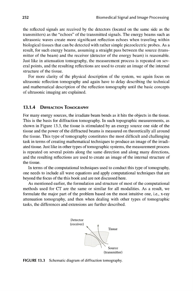
For many energy sources, the irradiate beam bends as it hits the objects in the tissue.
This is the basis for diffraction tomography. In such topographic measurements, as
shown in Figure 13.3, the tissue is stimulated by an energy source one side of the
tissue and the power of the diffracted beams is measured on theoretically all around
the tissue. This type of tomography constitutes the most difficult and challenging
task in terms of creating mathematical techniques to produce an image of the irradiated tissue. Just like in other types of tomographic systems, the measurement process
is repeated on several points along the same direction and along many directions,
and the resulting reflections are used to create an image of the internal structure of
the tissue.
In terms of the computational techniques used to conduct this type of tomography,
one needs to include all wave equations and apply computational techniques that are
beyond the focus of the this book and are not discussed here.
As mentioned earlier, the formulation and structure of most of the computational
methods used for CT are the same or similar for all modalities. As a result, we
formulate the major part of the problem based on the most intuitive one, i.e., x-ray
attenuation tomography, and then when dealing with other types of tomographic
tasks, the differences and extensions are further described.
Detector
(transmitter)
(receiver)
Tissue
Source
FIGURE 13.3 Schematic diagram of diffraction tomography.
Biomedical Signal and Image Processing
the reflected signals are received by the detectors (located on the same side as the
transmitters) as the “echoes” of the transmitted signals. The energy beams such as
ultrasonic waves create more significant reflection echoes when traveling within
biological tissues that can be detected with rather simple piezoelectric probes. As a
result, for such energy beams, assuming a straight pass between the source (transmitter of the beam) and the receiver (detector of the energy beam) is reasonable.
Just like in attenuation tomography, the measurement process is repeated on several points, and the resulting reflections are used to create an image of the internal
structure of the tissue.
For more clarity of the physical description of the system, we again focus on
ultrasonic reflection tomography and again have to delay describing the technical
and mathematical description of the reflection tomography until the basic concepts
of ultrasonic imaging are explained.
13.1.4 DIFFRACTION TOMOGRAPHY
For many energy sources, the irradiate beam bends as it hits the objects in the tissue.
This is the basis for diffraction tomography. In such topographic measurements, as
shown in Figure 13.3, the tissue is stimulated by an energy source one side of the
tissue and the power of the diffracted beams is measured on theoretically all around
the tissue. This type of tomography constitutes the most difficult and challenging
task in terms of creating mathematical techniques to produce an image of the irradiated tissue. Just like in other types of tomographic systems, the measurement process
is repeated on several points along the same direction and along many directions,
and the resulting reflections are used to create an image of the internal structure of
the tissue.
In terms of the computational techniques used to conduct this type of tomography,
one needs to include all wave equations and apply computational techniques that are
beyond the focus of the this book and are not discussed here.
As mentioned earlier, the formulation and structure of most of the computational
methods used for CT are the same or similar for all modalities. As a result, we
formulate the major part of the problem based on the most intuitive one, i.e., x-ray
attenuation tomography, and then when dealing with other types of tomographic
tasks, the differences and extensions are further described.
Detector
(transmitter)
(receiver)
Tissue
Source
FIGURE 13.3 Schematic diagram of diffraction tomography.