

251
Principles of Computed Tomography
amount of reflection or refraction. On the other hand, for medical ultrasonic waves,
the typical wavelength is in the order of a few millimeters and therefore will produce
significant echoes and diffraction.
Returning to the mechanism of attenuation tomography, often, the process of
irradiation on one side and measurement on the other side is repeated on several
points along the same direction (i.e., parallel lines in Figure 13.1a) and along many
directions (Figure 13.1b), and the resulting attenuation values are used to create an
image of the internal structure of the tissue.
13.1.2 TIME-OF-FLIGHT TOMOGRAPHY
In the description of attenuation tomography, we did not use the concept of the time
needed for beams to pass through different tissues as a means of tomography. This is
due to the fact that in some image modalities such as x-ray, due to very high speed of
the beam (speed of light for x-ray), it is extremely difficult to measure the very short
time periods often encountered. In many such cases, designing hardware to measure
such short time intervals is practically impossible. However, in some image modalities, such as ultrasonic imaging, the speed of the propagation of the energy is rather
low, and we have the means (e.g., hardware) to measure the resulting time intervals.
For such technologies, a different type of tomography is often used that creates an
image of the tissue based on the differences in the speed of the energy beam in
different objects inside the tissue or, equivalently, the time it takes for the beam to
“fly” through different objects. Time-of-flight or TOF tomography is a popular technology
that is described here.
In order to better describe the physical concepts involved in this type of
tomography, we postpone describing this technique until the chapter on ultrasonic imaging. However, the principle techniques are applicable to all types of
image modality.
13.1.3 REFLECTION TOMOGRAPHY
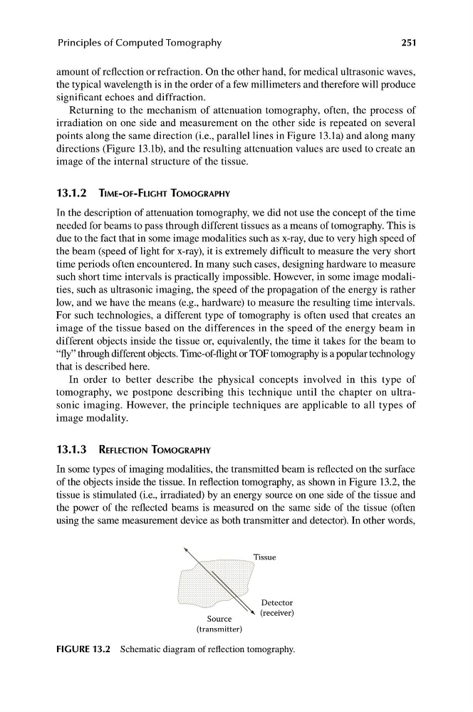
In some types of imaging modalities, the transmitted beam is reflected on the surface
of the objects inside the tissue. In reflection tomography, as shown in Figure 13.2, the
tissue is stimulated (i.e., irradiated) by an energy source on one side of the tissue and
the power of the reflected beams is measured on the same side of the tissue (often
using the same measurement device as both transmitter and detector). In other words,
Detector
(receiver)
Tissue
Source
(transmitter)
FIGURE 13.2 Schematic diagram of reflection tomography.
Principles of Computed Tomography
amount of reflection or refraction. On the other hand, for medical ultrasonic waves,
the typical wavelength is in the order of a few millimeters and therefore will produce
significant echoes and diffraction.
Returning to the mechanism of attenuation tomography, often, the process of
irradiation on one side and measurement on the other side is repeated on several
points along the same direction (i.e., parallel lines in Figure 13.1a) and along many
directions (Figure 13.1b), and the resulting attenuation values are used to create an
image of the internal structure of the tissue.
13.1.2 TIME-OF-FLIGHT TOMOGRAPHY
In the description of attenuation tomography, we did not use the concept of the time
needed for beams to pass through different tissues as a means of tomography. This is
due to the fact that in some image modalities such as x-ray, due to very high speed of
the beam (speed of light for x-ray), it is extremely difficult to measure the very short
time periods often encountered. In many such cases, designing hardware to measure
such short time intervals is practically impossible. However, in some image modalities, such as ultrasonic imaging, the speed of the propagation of the energy is rather
low, and we have the means (e.g., hardware) to measure the resulting time intervals.
For such technologies, a different type of tomography is often used that creates an
image of the tissue based on the differences in the speed of the energy beam in
different objects inside the tissue or, equivalently, the time it takes for the beam to
“fly” through different objects. Time-of-flight or TOF tomography is a popular technology
that is described here.
In order to better describe the physical concepts involved in this type of
tomography, we postpone describing this technique until the chapter on ultrasonic imaging. However, the principle techniques are applicable to all types of
image modality.
13.1.3 REFLECTION TOMOGRAPHY
In some types of imaging modalities, the transmitted beam is reflected on the surface
of the objects inside the tissue. In reflection tomography, as shown in Figure 13.2, the
tissue is stimulated (i.e., irradiated) by an energy source on one side of the tissue and
the power of the reflected beams is measured on the same side of the tissue (often
using the same measurement device as both transmitter and detector). In other words,
Detector
(receiver)
Tissue
Source
(transmitter)
FIGURE 13.2 Schematic diagram of reflection tomography.