

To proceed with the development of different cage models the area between the
three piles of the tripile geometrically usable was taken into account for the maximum size of the cage (Figs. 11.34d and 11.35a–c). Additionally, the cage had to be
planned in a size that would fit between the piles to get it in and out for installation,
maintenance and repair. Therefore, next to the size of the cage the coupling between
cage and piles had to be planned as well to get the maximum dimension of the
entire cage construction. The following additional parameters and characteristics
were taken into account during the fundamental development phase:
(1) simple cage design with only a few crossbars to ease construction and
installation,
(2) the height of the cage depends on the depth of the water to allow fully submergence and also the draught (up to 8 m) of the maintenance vessels when
accessing the wind turbine (Figs. 11.35d 11.38a, b, e, f),
(3) the attachment mechanism (e.g. rails) mounted exteriorly of the cage to avoid
any interference with the net,
(4) optimizing the coupling design symptoms of fatigue that were not primarily
considered as the malfunction of the maximum load on it,
(5) the attachment device should not interfere with the sacrificial anode at the piles,
(6) the cage should be additionally fixed to the support cross and to an anchor at the
seafloor,
(7) the coupling of the cage with the pile can be realized via rigid or flexible
attachments or independently via an external mooring. The various options were
reduced to a rigid attachment to the piles of the offshore wind energy foundation,
as flexible couplings via ropes or cables could lead to an entanglement,
(8) to allow a preferably large surface area for flatfish to settle. Therefore, additional plane levels were integrated into the inner parts of the cage, which also
supported the bracing of the cage and therefore supported structural stability,
even if the conditions of production were more complicated as well as the loads
on the entire cage induced through currents and waves,
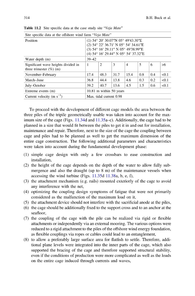
Table 11.2 Site specific data at the case study site “Veja Mate”
Site specific data at the offshore wind farm “Veja Mate”
Position
(1) 54° 20′ 30.07″N 05° 49′43.30″E
(2) 54° 22′ 36.71′ N 05° 54′ 34.61″E
(3) 54° 16′ 29.11″ N 05° 49′38.99″E
(4) 54° 16′ 29.44″ N 05° 54′ 37.32″E
Water depth (m)
39–42
Significant wave heights divided in
three trimester (%) (m)
1
2
3
4
5
6
> 6
November–February
17.4
48.3
31.7
15.4
0.8
0.4
<0.1
March–June
36.8
44.4
13.8
4.6
0.3
0.2
<0.1
July–October
39.2
40.7
13.6
4.5
1.5
0.6
<0.1
Extreme events (m)
10.81 m within 50 years
Current velocity (m s
−1
)
Max. tidal current 0.98
314
B.H. Buck et al.
three piles of the tripile geometrically usable was taken into account for the maximum size of the cage (Figs. 11.34d and 11.35a–c). Additionally, the cage had to be
planned in a size that would fit between the piles to get it in and out for installation,
maintenance and repair. Therefore, next to the size of the cage the coupling between
cage and piles had to be planned as well to get the maximum dimension of the
entire cage construction. The following additional parameters and characteristics
were taken into account during the fundamental development phase:
(1) simple cage design with only a few crossbars to ease construction and
installation,
(2) the height of the cage depends on the depth of the water to allow fully submergence and also the draught (up to 8 m) of the maintenance vessels when
accessing the wind turbine (Figs. 11.35d 11.38a, b, e, f),
(3) the attachment mechanism (e.g. rails) mounted exteriorly of the cage to avoid
any interference with the net,
(4) optimizing the coupling design symptoms of fatigue that were not primarily
considered as the malfunction of the maximum load on it,
(5) the attachment device should not interfere with the sacrificial anode at the piles,
(6) the cage should be additionally fixed to the support cross and to an anchor at the
seafloor,
(7) the coupling of the cage with the pile can be realized via rigid or flexible
attachments or independently via an external mooring. The various options were
reduced to a rigid attachment to the piles of the offshore wind energy foundation,
as flexible couplings via ropes or cables could lead to an entanglement,
(8) to allow a preferably large surface area for flatfish to settle. Therefore, additional plane levels were integrated into the inner parts of the cage, which also
supported the bracing of the cage and therefore supported structural stability,
even if the conditions of production were more complicated as well as the loads
on the entire cage induced through currents and waves,
Table 11.2 Site specific data at the case study site “Veja Mate”
Site specific data at the offshore wind farm “Veja Mate”
Position
(1) 54° 20′ 30.07″N 05° 49′43.30″E
(2) 54° 22′ 36.71′ N 05° 54′ 34.61″E
(3) 54° 16′ 29.11″ N 05° 49′38.99″E
(4) 54° 16′ 29.44″ N 05° 54′ 37.32″E
Water depth (m)
39–42
Significant wave heights divided in
three trimester (%) (m)
1
2
3
4
5
6
> 6
November–February
17.4
48.3
31.7
15.4
0.8
0.4
<0.1
March–June
36.8
44.4
13.8
4.6
0.3
0.2
<0.1
July–October
39.2
40.7
13.6
4.5
1.5
0.6
<0.1
Extreme events (m)
10.81 m within 50 years
Current velocity (m s
−1
)
Max. tidal current 0.98
314
B.H. Buck et al.